_Win_Mac.png)
Sample 1. Network Diagramming Software
Design Elements — Network Layout (Windows, Macintosh).
Network Communication Plan library of vector stencils from Computer and Networks solution provides the 19 objects of design element for drawing the computer network layout diagrams.
Use Network Communication Plan library to create your own network layout diagrams that show LAN and WAN architecture, topology and design against the floor plans.
TEN RELATED HOW TO's:
Wireless Network solution contains template, library and a set of design elements that help network engineers visualize Wireless Network. Network engineers and designers use this solution to design, create and illustrate the wireless networks.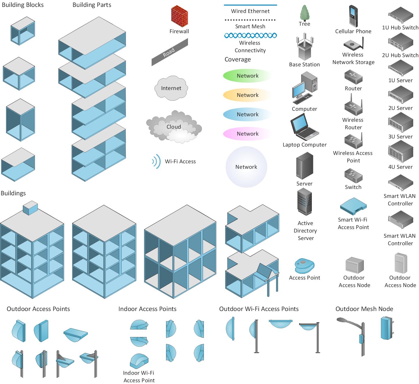
Picture: ConceptDraw DIAGRAM is an Advanced tool for Professional Network Diagrams Creation
Related Solution:
The Cisco Network Diagrams solution from the Computer and Networks area of ConceptDraw Solution Park provides a wide collection of predesigned templates and samples that help you to create the Cisco Network Diagrams in one moment.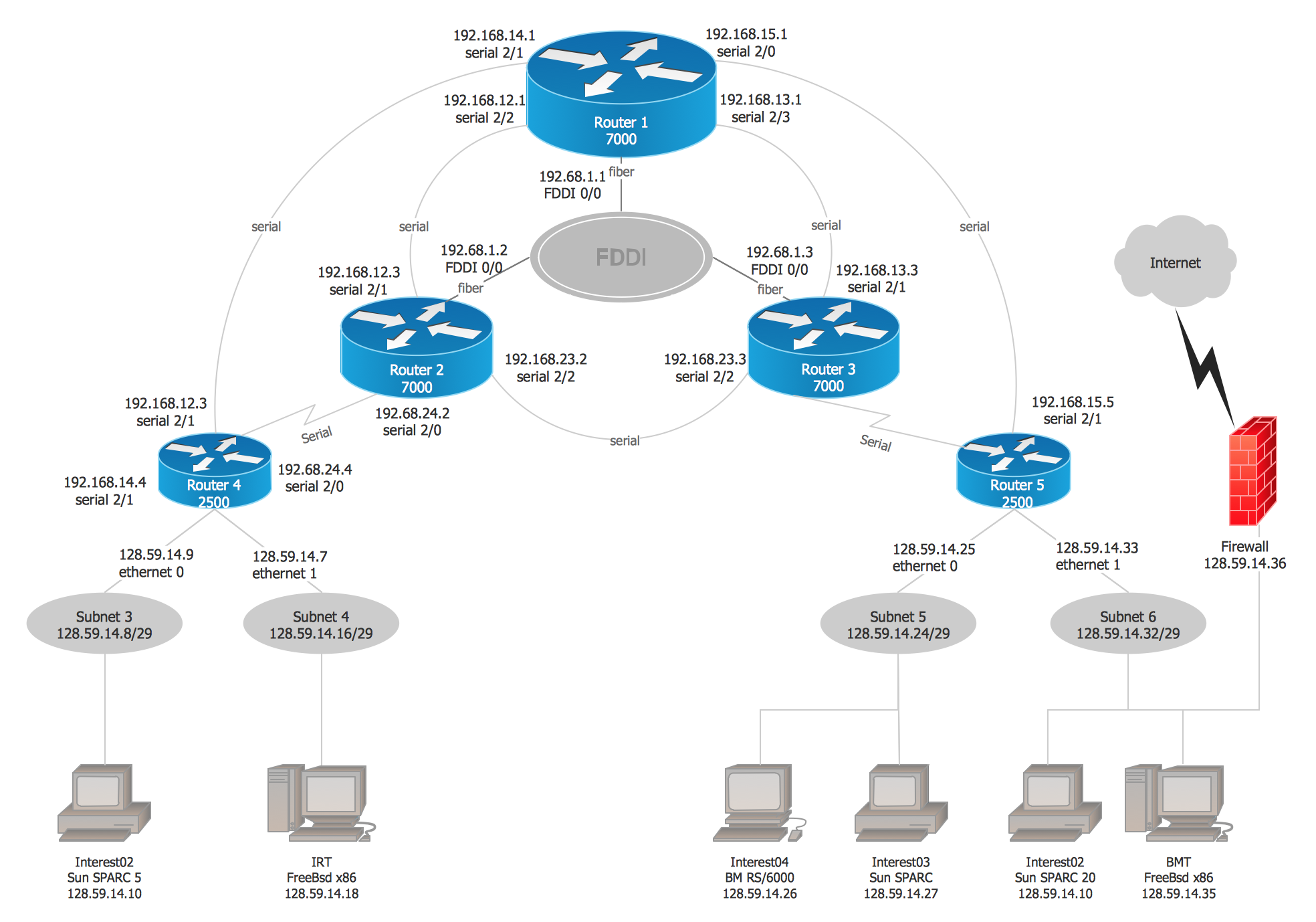
Picture: Cisco Network Examples and Templates
Related Solution:
When searching for a diagramming tool, we look for a powerful and reliable software that would be easy to use. To mention one, ConceptDraw DIAGRAM has all the necessary features to create cross-functional flowcharts (Swim Lanes) quick and effortlessly. You can draw swim lane diagrams in both vertical and horizontal ways.
This cross-functional flowchart displays a payroll process. It explains to each participant his role in the process depending on the category, represented with swimlanes. Using this flowchart, every employee can easily find out what he can expect in terms of salary. Generally a cross-functional diagram enables one to take a look at processes with a wider scope and with more precision than simple flowchart. Business process capturing using cross-functional flowcharts can be useful for stakeholders and managers to define clearly the staff's roles and responsibilities.
Picture: Cross-Functional Flowchart (Swim Lanes)
Related Solution:
The Entity-Relationship Diagram (ERD) solution from ConceptDraw Solution Park extends ConceptDraw DIAGRAM vector graphics and diagramming software with the ability to describe a database using the Entity-Relationship (Chen) model. Use it for design your ERDs and verify that ConceptDraw DIAGRAM offers the best ERD diagrams software tools for design element Chen notation._Win_Mac.png)
Picture: Entity Relationship Diagram - ERD - Software for Design Chen ER Diagrams
Related Solution:
System administrators of the whole world successfully use the Active Directory Domain Services. ConceptDraw DIAGRAM offers the Active Directory Diagrams Solution from the Computer and Networks Area with powerful drawing tools developed specially for all specialists which need create various active directory domain diagrams in their work activity.
Picture: Active Directory Domain
Related Solution:
A layout is a way that furniture is arranged in some place. It’s not difficult to develop a store layout using software with tons of templates and libraries with vector shapes of furniture, doors, walls etc. Create a plan in five minutes and have more time to implement it.
Designing the floor plan for a new store is very important step for a small business. Well thought out and well-done floor plan is the foundation of the store layout. It should provide a basis through which to make out and organize everything else. Sometimes a small stores have a small floor space, so well thought out arrangement of furniture and commercial equipment is crucial to the success of the business. By using the ConceptDraw Floor Plans solution you can make a floor plan for your store quickly and effortlessly.
Picture: Store Layout Software
Related Solution:
It is easy to recreate any informational system structure using diagrams. There are three main components of any ER diagram: entity, attribute and relationship. Basing on these three components, one can define other, less used elements, such as weak entity or relationship, derived attribute, recursive relationship etc.
This is the set of graphic elements of ERD Chen's notation. This ERD notation is used to represent an entity–relationship models. It involves the set of geometric forms: rectangles - depicting entities, ovals - representing attributes and diamonds depicting relationships assigned for first-class objects, that can have relationships and attributes of their own. Connections are displayed with arrowed lines. It is known that the Chen's ERD notation is used to show a detailed view of entities and relationships. ConceptDraw Entity-Relationship Diagram solution from the Software Development section of Solution Park provides the ability to create ERD of database structure for software development purposes using the Chen’s notation elements.
Picture: Components of ER Diagram
Related Solution:
Have you ever wanted to start your own cafe? To imagine any possible options, try Cafe Floor Plan Design Software now for free 21 day trial. This will allow you to use all the ConceptDraw DIAGRAM main features.
Here is an example of a multi-page document consisting from the various options of interior design and plans for arranging a cafe. This document can be used as a basis for the development of a professional designer portfolio. It was drawn using ConceptDraw Cafe and Restaurant Plans solution. The solution supplies vector libraries, templates and samples that are released to assist amateurs and professionals to draw the i designs of interior and furniture layouts of the cafe hall and lobby.
Picture: How to create Cafe Floor Plan Design
Related Solution:
ConceptDraw DIAGRAM is the professional business graphic software for drawing diagrams and charts with great visual appeal on Mac OS X.
Picture: The Best Drawing Program for Mac
Related Solution:
Nature solution expands this software possibilities to create beautiful illustrations diagrams with the new library which contains 17 vector objects.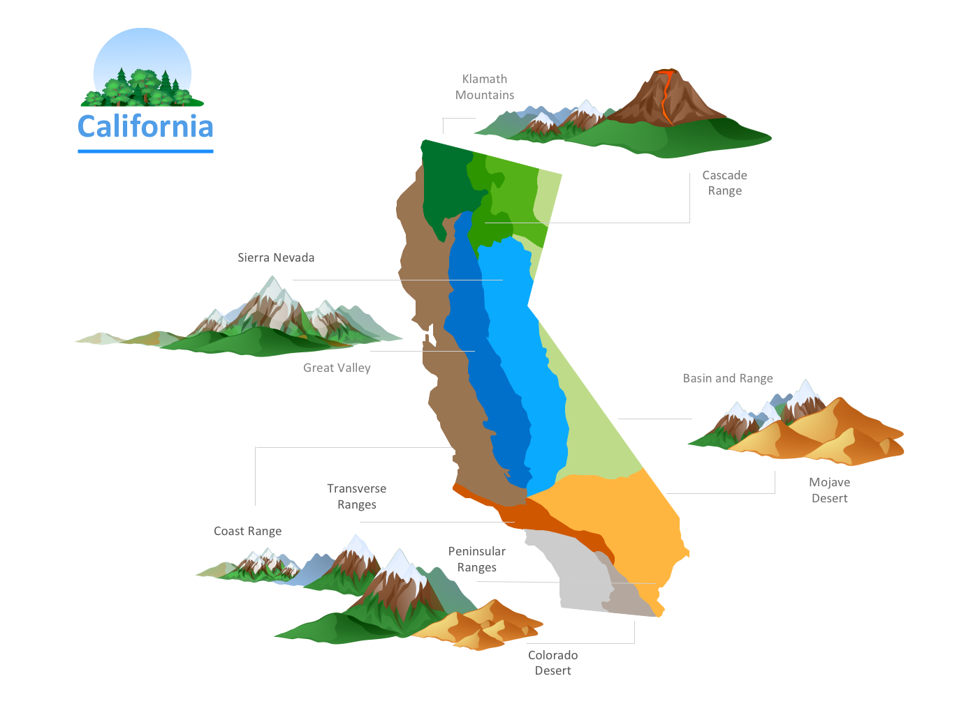
Picture: Nature Drawings - How to Draw