Metropolitan area networks (MAN). Computer and Network Examples
. Computer and Network Examples")

Local area network (LAN). Computer and Network Examples
 diagram")
Personal area (PAN) networks. Computer and Network Examples
 networks")
Campus Area Networks (CAN). Computer and Network Examples
. <br>Computer and Network Examples *")
Entity Relationship Diagram Symbols

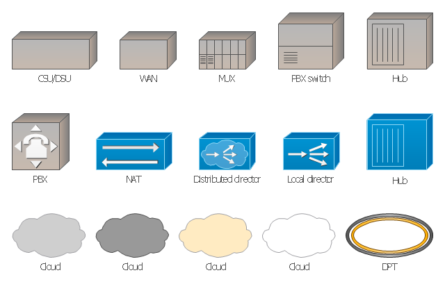
The vector stencils library "Cisco WAN" contains 15 symbols of wide area network (WAN) devices and equipment: CSU/ DSU (Channel Service Unit/ Data Service Unit), WAN, MUX (multiplexer), PBX switch, Hub, NAT (network address translation), distributed and local directors, PBX (private branch exchange), Network clouds, DPT (dynamic packet transport).
Create the computer network topology diagrams using the ConceptDraw PRO diagramming and vector drawing software with the design elements library "Cisco WAN".
"A wide area network (WAN) is a network that covers a broad area (i.e., any telecommunications network that links across metropolitan, regional, or national boundaries) using private or public network transports. Business and government entities utilize WANs to relay data among employees, clients, buyers, and suppliers from various geographical locations. In essence, this mode of telecommunication allows a business to effectively carry out its daily function regardless of location. The Internet can be considered a WAN as well, and is used by businesses, governments, organizations, and individuals for almost any purpose imaginable.
Related terms for other types of networks are personal area networks (PANs), local area networks (LANs), campus area networks (CANs), or metropolitan area networks (MANs) which are usually limited to a room, building, campus or specific metropolitan area (e.g., a city) respectively." [Wide area network. Wikipedia]
The example "Design elements - Cisco WAN" is included in the Cisco Network Diagrams solution from the Computer and Networks area of ConceptDraw Solution Park.
Cisco WAN symbols
Hybrid Network Topology

Network Topologies


ATM Network. Computer and Network Examples

Cisco Routers. Cisco icons, shapes, stencils and symbols

Network Community Structure. Computer and Network Examples

Server

How to Draw a Computer Network Diagrams

Network Glossary Definition

Network Components

Business - Design Elements

Ring Network Topology

Data Flow Diagrams

Example of DFD for Online Store (Data Flow Diagram)


"In computer networks, networked computing devices pass data to each other along data connections. The connections (network links) between nodes are established using either cable media or wireless media. ...
Network computer devices that originate, route and terminate the data are called network nodes. Nodes can include hosts such as personal computers, phones, servers as well as networking hardware. ...
Network links.
The communication media used to link devices to form a computer network include electrical cable (HomePNA, power line communication, G.hn), optical fiber (fiber-optic communication), and radio waves (wireless networking). In the OSI model, these are defined at layers 1 and 2 - the physical layer and the data link layer.
A widely adopted family of communication media used in local area network (LAN) technology is collectively known as Ethernet. The media and protocol standards that enable communication between networked devices over Ethernet are defined by IEEE 802.3. Ethernet transmit data over both copper and fiber cables. Wireless LAN standards (e.g. those defined by IEEE 802.11) use radio waves, or others use infrared signals as a transmission medium. Power line communication uses a building's power cabling to transmit data. ...
Network nodes.
Apart from the physical communications media described above, networks comprise additional basic system building blocks, such as network interface controller (NICs), repeaters, hubs, bridges, switches, routers, modems, and firewalls." [Computer network. Wikipedia]
The network equipment and cabling layout floorplan template for the ConceptDraw PRO diagramming and vector drawing software is included in the Network Layout Floor Plans solution from the Computer and Networks area of ConceptDraw Solution Park.
LAN equipment and cabling layout floorplan template

- Explain Metropolitan Area Network In Detail
- Metropolitan area networks (MAN). Computer and Network Examples
- What Is Meaning Of Metropolitan Area Network And Define
- Cisco LAN - Vector stencils library | Metropolitant Area Network
- Network Topologies | Explain Campus Area Network
- Metropolitan area networks (MAN). Computer and Network Examples
- Metropolitan area networks (MAN). Computer and Network Examples
- Campus Area Networks (CAN). Computer and Network Examples ...
- Personal area (PAN) networks . Computer and Network Examples ...
- Network Diagram Examples | Network Diagramming with ...
- Campus Network Definition
- Wide area network (WAN) topology. Computer and Network Examples
- Local area network (LAN). Computer and Network Examples ...
- Metropolitan area networks (MAN). Computer and Network ...
- Metropolitan area networks (MAN). Computer and Network ...
- Metropolitan area networks (MAN). Computer and Network Examples
- Metropolitan area networks (MAN). Computer and Network Examples
- Metropolitan area networks (MAN). Computer and Network ...
- Local area network (LAN). Computer and Network Examples ...