Electrical Symbols, Electrical Diagram Symbols

Electrical Symbols — Rotating Equipment

Mechanical Drawing Symbols

Interior Design. Machines and Equipment — Design Elements

Electrical Symbols — Semiconductor

Electrical Symbols — Inductors

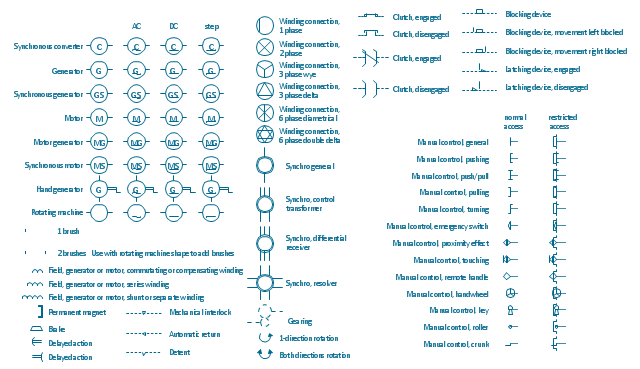
The vector stencils lybrary "Rotating equipment" contains 55 symbols of rotating equipment: converters, generators, motors, rotating machines, and their parts and labels.
Use to design systems containing rotating electrical equipment (i.e., motors), armatures, brushes, and related mechanical devices ( brakes, gearing, clutches, interlocks).
"The academic study of electric machines is the universal study of electric motors and electric generators. By the classic definition, electric machine is synonymous with electric motor or electric generator, all of which are electromechanical energy converters: converting electricity to mechanical power (i.e., electric motor) or mechanical power to electricity (i.e., electric generator). The movement involved in the mechanical power can be rotating or linear.
Although transformers do not contain any moving parts they are also included in the family of electric machines because they utilise electromagnetic phenomena.
Electric machines (i.e., electric motors) consume approximately 60% of all electricity produced. Electric machines (i.e., electric generators) produce virtually all electricity consumed. Electric machines have become so ubiquitous that they are virtually overlooked as an integral component of the entire electricity infrastructure. Developing ever more efficient electric machine technology and influencing their use are crucial to any global conservation, green energy, or alternative energy strategy." [Electric machine. Wikipedia]
The shapes example "Design elements - Rotating equipment" was drawn using the ConceptDraw PRO diagramming and vector drawing software extended with the Electrical Engineering solution from the Engineering area of ConceptDraw Solution Park.
Rotating equipment symbols
UML State Machine Diagram.Design Elements

Electrical Drawing Software and Electrical Symbols

Electrical Symbols — Electrical Circuits

Electrical Symbols — Power Sources

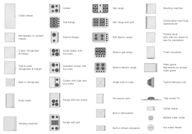
The vector stencils library Appliances contains 36 symbols of kitchen appliances, laundry appliances, stoves, cooking appliances, and laundry equipment.
Use the shapes library Appliances to draw equipment layouts and interior design floor plans of kitchens, laundry rooms, utility rooms using the ConceptDraw PRO diagramming and vector drawing software.
"Home appliances are electrical/ mechanical machines which accomplish some household functions, such as cooking or cleaning. Home appliances can be classified into:
Major appliances, or White goods;
Small appliances, or Brown goods;
Consumer electronics, or Shiny goods.
White goods/ major appliances comprise major household appliances and may include: air conditioner, dishwasher, clothes dryer, drying cabinet, freezer, refrigerator, kitchen stove, water heater, washing machine, trash compactor, microwave ovens and induction cookers.
Brown goods/ small appliances are typically small household electrical entertainment appliances such as: TV sets, CD and DVD players, camcorders, still cameras, clocks, alarm clocks, video game consoles, HiFi and home cinema, telephones and answering machines.
Consumer electronics (abbreviated CE) are electronic equipment intended for everyday use, most often in entertainment, communications and office productivity. Main products include radio receivers, television sets, MP3 players, video recorders, DVD players, digital cameras, camcorders, personal computers, video game consoles, telephones and mobile phones." [Home appliance. Wikipedia]
The design elements library Appliances is provided by the Floor Plans solution from the Building Plans area of ConceptDraw Solution Park.
Process Flow Diagram Symbols

How To Create Emergency Plans and Fire Evacuation

Electrical Symbols — Thermo

Telecom Wireless Plan

Electrical Symbols — Lamps, Acoustics, Readouts

Electrical and Telecom Plan Software

Wiring Diagrams with ConceptDraw DIAGRAM

Electrical Symbols — Terminals and Connectors

- Electrical Symbols — Rotating Equipment | Electrical Symbols ...
- Mechanical Drawing Symbols | Electrical Symbols, Electrical ...
- Computers and Communications | Electrical Machine Lab Layout ...
- Electrical Equipment Devices Draw And Label The Parts In Electricity
- Electrical Machine Tree Diagram
- Electric Machine Symsbol Pdf File
- Process Flow Diagram Symbols | Mechanical Drawing Symbols ...
- Symbol For Washing Machine On Floor Plans
- Electrical Symbols, Electrical Diagram Symbols | Technical Drawing ...
- Mechanical Drawing Symbols | Electrical Symbols, Electrical ...
- Technical drawing - Machine parts assembling | Mechanical ...
- Electrical Symbols, Electrical Diagram Symbols | Electrical Symbols ...
- Electrical Press Machine Drawing
- Electrical Symbols, Electrical Diagram Symbols | Electrical Symbols ...
- Machine Drawing Samples
- Mechanical Drawing Symbols | Electrical Symbols, Electrical ...
- Electrical Machine Design Flow Chart
- Www Machine Drawing Enginee Diagram Com
- Star Network Topology | Cnc Mc Electrical Drawings Symbol