Mechanical Drawing Symbols F.A.Q. How to Use Mechanical Engineering Design Software
Mechanical design involves designing parts, components, products, and systems of a mechanical nature. Detailed and precise mechanical designs are used in manufacturing, creating specifications, and completing statements of functions. Both mechanical designers and mechanical engineers play crucial roles in designing drawings for devices, systems, equipment, and machinery. Because the development of new mechanical components, parts, products, equipment, and systems is impossible without clear documentation. Moreover, the mechanical designers base their designs on the sketches made by mechanical engineers and transform their sketches into precise technical designs ready for manufacturing.
Mechanical designs help streamline and improve manufacturing processes to produce high-quality, reliable, and durable equipment, mechanical products and systems. They help to reduce time-to-market for mechanical products and analyze the interaction of components, test their combinations to have a possibility to fix errors and inaccuracies, change some details, designs, or materials without producing a physical prototype, and enhance fault tolerance.
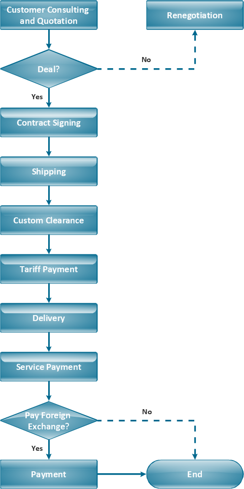
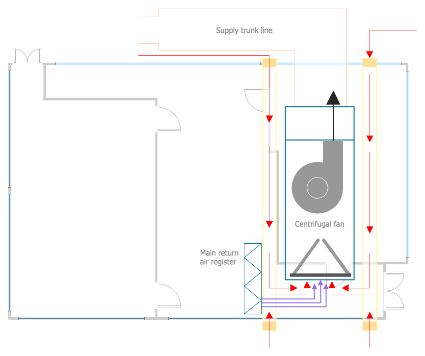
Mechanical systems drawing is a type of technical drawing that shows information about heating, ventilating, and air conditioning. It is a powerful tool that helps analyze complex systems. These drawings are often a set of detailed drawings used for construction projects; it is a requirement for all HVAC work. They are based on the floor and reflected ceiling plans of the architect. After the mechanical drawings are complete, they become part of the construction drawings, which is then used to apply for a building permit. They are also used to determine the price of the project.

Example 1. Mechanical Engineering — Directional Control Valve
Common Mechanical Drawing Symbols
Mechanical design is an important step in creating and designing mechanical elements, components, products, and systems. Its precision, clarity, and thoughtfulness play a vital role in the development and manufacturing of a wide range of mechanical products and systems.
Mechanical drawings, schematics, diagrams, plans, and maps are constructed using special graphical symbols, generally accepted in mechanical engineering. This helps to make technical documentation comprehensible and usable for all technical specialists and mechanical engineers.
Standard Symbols for Mechanical Components
Symbols in mechanical drawings are graphical elements accepted by standards and codes. They represent components, elements, details, characteristics, actions, features, and conditions important for a defined technical product or system. Standard symbols for mechanical components use such shapes as circles, ovals, arcs, triangles, squares, rectangles, polygons, lines, arrows, and other geometrical forms separately or arranged in complex patterns.
Mechanical engineering symbols help to display structure, mechanical links, connections, guiding controls, constraints, motion, and operation principles. They help engineers to understand and interpret displayed information correctly, convey information quickly and accurately, indicate all important attributes, save space, avoid repetition, and make mechanical drawings clear, comprehensible, and relevant to standards and codes.
Key Symbols for Measurements and Tolerances
Measuring mechanical components is one of the crucial tasks in mechanical engineering. Measurement accuracy is important and all characteristics, such as dimensions, tolerances, and shapes of the parts have a value, especially for the complex mechanical components with irregular forms. Because all manufacturing methods are not flawless, the engineering tolerances are provided.
Tolerance is the acceptable variation in a specific measurement from the base measurement, assigned dimensions or geometry, the difference between the maximal and minimal limits. It is inherent to engineering and mechanical engineering and is applied to angular, linear, and other physical dimensions of mechanical components. Usually, the tolerances are expressed as direct limits, geometric tolerances, or notes.
Overview of ConceptDraw Mechanical Engineering Design Software
Mechanical designs help streamline and improve manufacturing processes. and mechanical engineering design software helps to produce high-quality, reliable, and durable mechanical components, products, equipment, and systems. Because having a visual design you can analyze and optimize your product, test the interaction of components, and make changes if required on the stage of design and development, fix errors and inaccuracies, change some components, etc.
Working as a mechanic being responsible for making the appropriate drawings, including technical ones, working with ventilating, heating, or air conditioning, you may find it exhausting creating all of schemes by hand using the ruler, for example. The use of special mechanical design software assists in creating advanced and innovative mechanical designs. In this case, we can recommend downloading ConceptDraw DIAGRAM which is professional software that can make your life simpler and help you to achieve your goals at work in your business.
ConceptDraw DIAGRAM vector drawing software is one of the best mechanical drawing programs. Being extended with Mechanical Engineering solution from the Engineering area of ConceptDraw Solution Park, it provides a set of drawing tools and predesigned mechanical engineering symbols and machinist symbols for fast and easy design various mechanical engineering diagrams, drawings, and schematics.
Features and Capabilities
ConceptDraw DIAGRAM provides numerous features and powerful capabilities:
- data visualization
- vector graphics
- visual flexibility
- libraries of predesigned vector stencils
- user-friendly drag & drop capabilities
- collection of professionally designed samples
- customizable templates
- collaboration tools
- efficient team communication
- document management
- extensive data import/export
Example 2. Mechanical Engineering Design
Guide on Using Mechanical Drawing Symbols
Engineers and other technical professionals can use standardized mechanical drafting symbols and machinist symbols and abbreviations to construct their professional-looking diagrams easily and quickly. Being standardized, these symbols ensure clear communication and understanding between the different stakeholders involved in the mechanical manufacturing process. Simply drag and drop the desired stencils and symbols from the solution libraries to your document and arrange them in the required way. In this simple way your diagram will be ready quickly and easily.
Setting Up a Project in Mechanical Engineering Software
ConceptDraw DIAGRAM mechanical engineering design software provides comprehensive tools for designing, modeling, and multi-side setting up mechanical engineering projects. Engineers and designers have the perfect possibility to design and model parts and assemblies. The professional tools enhance your productivity and creativity, help to control and optimize your projects, plan materials and resources, make team collaboration and communication with suppliers and customers efficient.
ConceptDraw DIAGRAM is a mechanical drawing software that combines all tools needed to create drawings, diagrams, and plans to implement projects of any size on schedule. It is flexible and adaptable to your requirements and methods, supports you in scheduling and reporting, helps to achieve goals and avoid common mistakes.
Accessing and Inserting Mechanical Drawing Symbols
Mechanical Engineering Solution offers 602 commonly used mechanical drawing symbols and objects which are professionally designed and grouped in 8 libraries. ConceptDraw DIAGRAM users have access to all of them and can insert them into the drawing by simply dragging and dropping:
Bearings Library
The vector stencils library "Bearings" contains 59 symbols of ball bearings, roller bearings, shafts, springs, gears, hooks, spindles, and keys. Use it to design engineering drawings of machine tools and mechanical devices.

Dimensioning and Tolerancing Library
The vector stencils library "Dimensioning and Tolerancing" contains 45 symbols of geometric dimensions and mechanical tolerances, geometric symbols, callouts, and text boxes and inserts. Use these geometric dimensioning and tolerancing shapes to create annotated mechanical drawings.

Fluid Power — Equipment Library
The vector stencils library "Fluid Power Equipment" contains 113 symbols of hydraulic and pneumatic equipment including pumps, motors, air compressors, cylinders, meters, gauges, and actuators. Use it to design fluid power and hydraulic control systems.

Fluid Power — Valves Library
The vector stencils library "Fluid Power Valves" contains 93 symbols of pre-made hydraulic and pneumatic valves, including directional control valves, flow control valves, pressure control valves, and electrohydraulic and electro-pneumatic valves.

Hydraulic Pumps and Motors Library
The vector stencils library "Hydraulic Pumps and Motors" contains 74 symbols of hydraulic pump vector stencils, hydraulic motor symbols for engineering drawings of fluid power and hydraulic control systems.

Pneumatic Pumps and Motors Library
The vector stencils library "Pneumatic Pumps and Motors" contains 39 symbols of pneumatic pumps, motors, and pump motors for designing the engineering drawings of pneumatic circuits.

Valve Assembly Library
The vector stencils library "Valve Assembly" contains 141 symbols of pressure and flow regulators, flow direction indicators, controls, and symbols to design flow paths of control valves. Use these valve assembly shapes to design the engineering drawings of hydraulic and pneumatic valve assemblies in fluid power systems.

Welding
The vector stencils library "Welding" contains 38 welding joint symbols to identify fillets, contours, resistance seams, grooves, surfacing, and backing. Use it to indicate welding operations on working drawings.

Customizing Symbols for Project Specifics
In addition, ConceptDraw DIAGRAM provides wide capabilities for customizing library objects relative to project specifics. All objects included in solutions libraries are vector and easy to resize without loss of quality. You can change objects' styles and colors to make your mechanical drawings more interesting, bright, and attractive. You can add specific elements, text, arrange and modify mechanical engineering symbols and objects in any other required way using the numerous software tools.
Efficiency Tips for Using Mechanical Design Software
Mechanical design is easy with correctly chosen mechanical design software. The best choice is the design software with powerful drawing tools and included collection of pre-made symbols, clipart, pictograms, and other elements, and if they are vector, that is a great benefit. ConceptDraw DIAGRAM software extended with Mechanical Engineering solution and many other solutions fully meets the listed criteria, and in addition, is flexible and easy to use. Your correct choice can save you time, resources, and money, and you need no drawing skills to design a professionally-looking diagram.
Before starting drawing it is recommended to create a technical specification including the requirements and objectives of the product or project, assembly features, and visualization of how the components interact. It helps to design mechanical drawings reflecting all your ideas and expectations, and also outline the scope, budget, and timeline of the project. The precise mechanical drawing is a way to communicate ideas and avoid mistakes and misunderstandings. It is also the possibility to analyze your project, test, make revisions, and optimize before the implementation. Check the functionality, reliability, and performance of future mechanical mechanisms.
Observe the set of designing and diagramming tools offered by ConceptDraw DIAGRAM and choose the correct tool that corresponds to your needs and requirements. Use standard generally accepted components and objects included in the solution libraries to make comprehensive diagrams and ensure consistency and accuracy in your design. This saves you time and effort. However, you can also add your custom components.
To design your own Mechanical Drawing in ConceptDraw DIAGRAM in minutes, follow the next steps:
- create new ConceptDraw document,
- drag the required mechanical drawing symbols from the libraries,
- arrange and connect these objects,
- type the text and apply colors, if needed.
When working with any software, don't forget to save regularly your project and back up your work to keep it from losing.

Example 3. Mechanical Engineering Diagram — Hydraulic Circuits
Conclusion
ConceptDraw DIAGRAM is a powerful vector mechanical engineering design software. The included collection of predesigned mechanical drafting symbols, machining drawing symbols, and machinist symbols helps in drawing mechanical diagrams and schematics, mechanical drafting symbols chart or mechanical drawing quickly, easily, and effectively.
The mechanical engineering diagrams you see on this page show the power, capabilities, and professional results you can achieve using ConceptDraw DIAGRAM software and Mechanical Engineering Solution.
All source documents are vector graphic documents. They are available for reviewing, modifying, or converting to a variety of formats (PDF file, MS PowerPoint, MS Visio, and many other graphic formats) from the ConceptDraw STORE. The Mechanical Engineering Solution is available for all ConceptDraw DIAGRAM users.