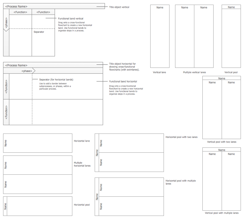
Example 1. Create Flowchart in ConceptDraw DIAGRAM software
Flowcharts Solution provides 2 libraries:
- Flowchart library - contains 26 ready-to-use predesigned vector objects,
- Flowcharts Rapid Draw library - contains 39 vector objects.
To create Flowchart in ConceptDraw DIAGRAM quickly and effectively:
- create ConceptDraw document,
- open the Flowchart or Flowcharts Rapid Draw library, simply drag-and-drop the needed objects from the library into your document,
- connect the objects in the needed order.
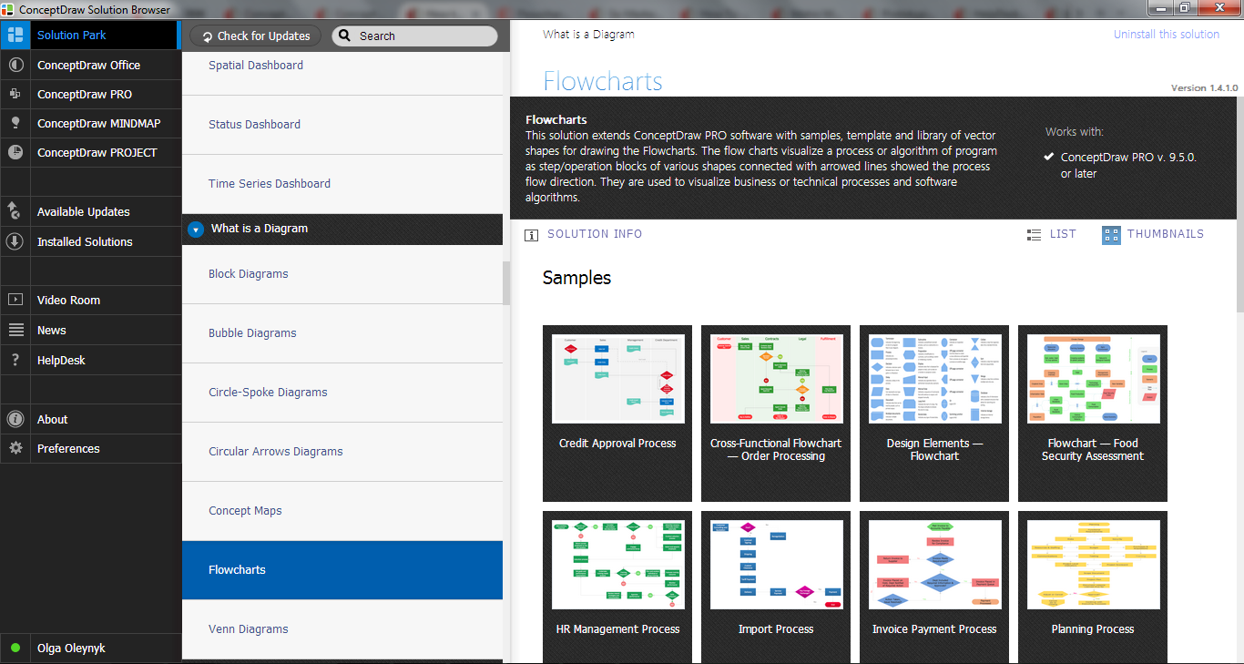
Example 2. Flowcharts Solution in ConceptDraw STORE
It’s very convenient to use the predefined template and samples from ConceptDraw STORE for creating the Flowchart Diagrams in one moment.
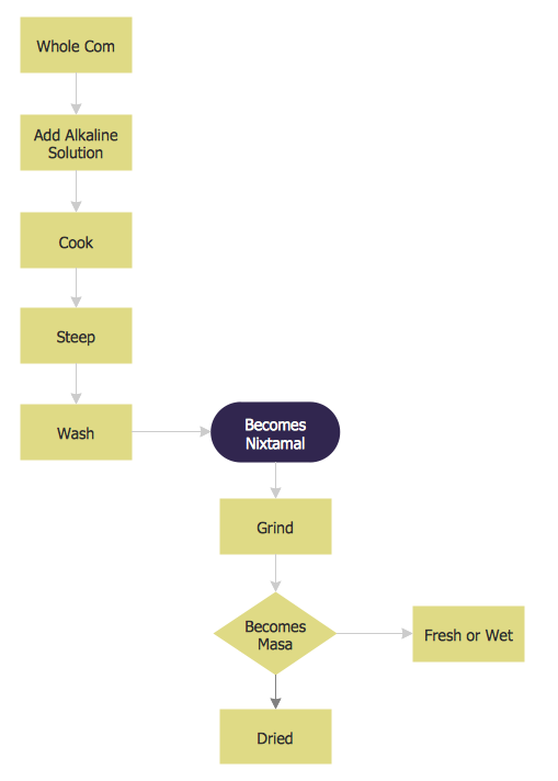
Example 3. Flowchart of Nixtamalization process
This example was redesigned from the Wikimedia Commons [commons.wikimedia.org]
This Flowchart Diagram of Nixtamalization and Masa production process was created in ConceptDraw DIAGRAM diagramming and vector drawing software using the Flowcharts solution from ConceptDraw Solution Park.
“Nixtamalization typically refers to a process for the preparation of maize (corn), or other grain, in which the grain is soaked and cooked in an alkaline solution, usually limewater, and hulled. Masa is Spanish for dough. In the Americas, it is often short for masa de maíz, a maize (corn) dough made from freshly prepared hominy.” [from Wikipedia]
Use the Flowcharts solution for ConceptDraw DIAGRAM software to create Flowchart Diagrams of any complexity quick and easy.
All source documents are vector graphic documents. They are available for reviewing, modifying, or converting to a variety of formats (PDF file, MS PowerPoint, MS Visio, and many other graphic formats) from the ConceptDraw STORE. The Flowcharts Solution is available for all ConceptDraw DIAGRAM or later users.
NINE RELATED HOW TO's:
Simple tutorial help you learn how to draw a scatter chart and increase you possibilities of understanding and work more effective with our scatter chart software.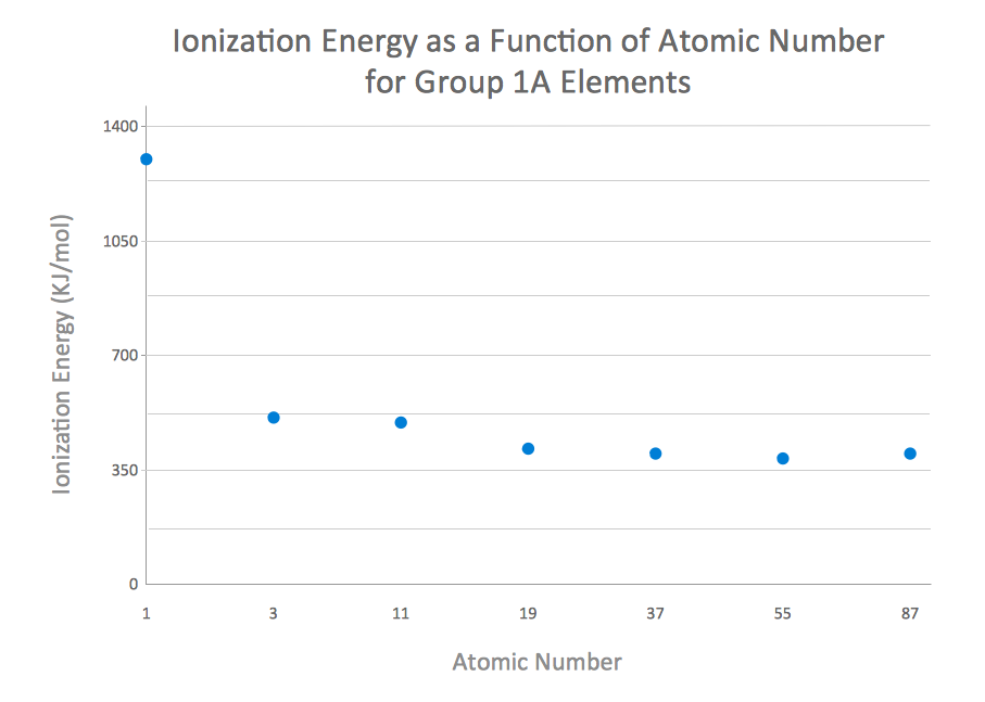
Picture: How to Create a Scatter Chart
Related Solution:
The Social Media Response solution provides the means to respond to social media mentions quickly and professionally. This tool keeps the entire team on the same page allowing you to realize your social media strategy, improve the quality of your answers, and minimize the time it takes to respond.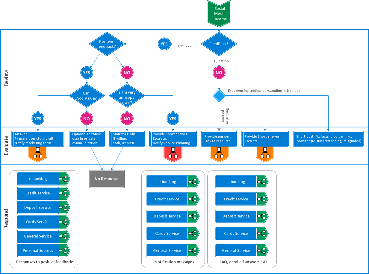
Picture: Manage Social Media Response Plan DFD
Related Solution:
Unified Modeling Language (UML) is a language of graphic description for object modeling in the field of software engineering. UML was created for definition, visualization, designing of software systems. UML is an open standard that uses graphic notations for creating visual models of object-oriented software systems.
The Rapid UML Solution for ConceptDraw DIAGRAM presentsthe intuitive RapidDraw interface that helps you to make the UML Diagram of any of these 13 types quick and easy.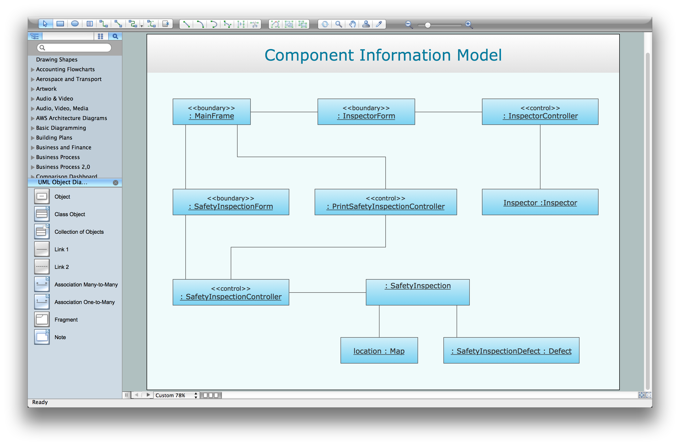
Picture: UML Software
Related Solution:
Create professional business process diagrams using ConceptDraw Data library with 10 objects from BPMN.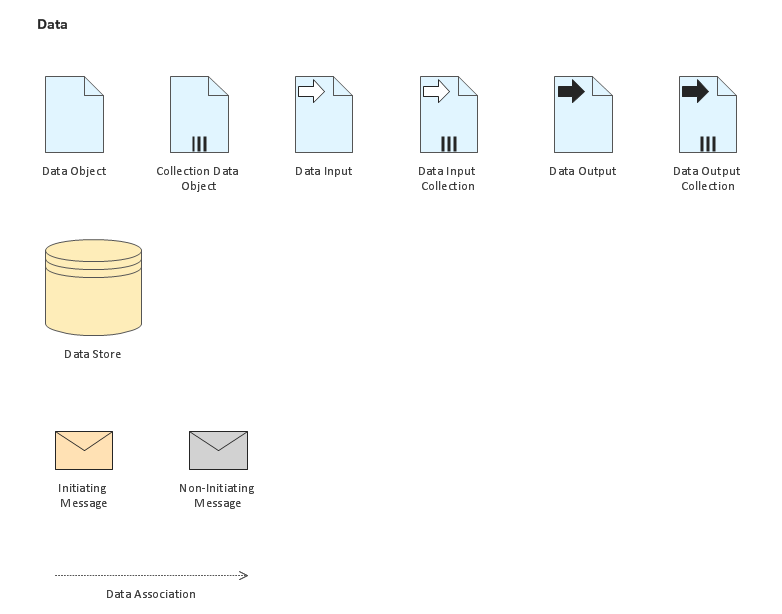
Picture: Business Process Elements: Data
Each business is created, exists and develops according to its type of business structure. Creating new business or developing existing, you may need a powerful software for representing its business structure. In this case ConceptDraw DIAGRAM diagramming and vector drawing software extended with 25 Typical Orgcharts solution from the Management area is exactly what you need.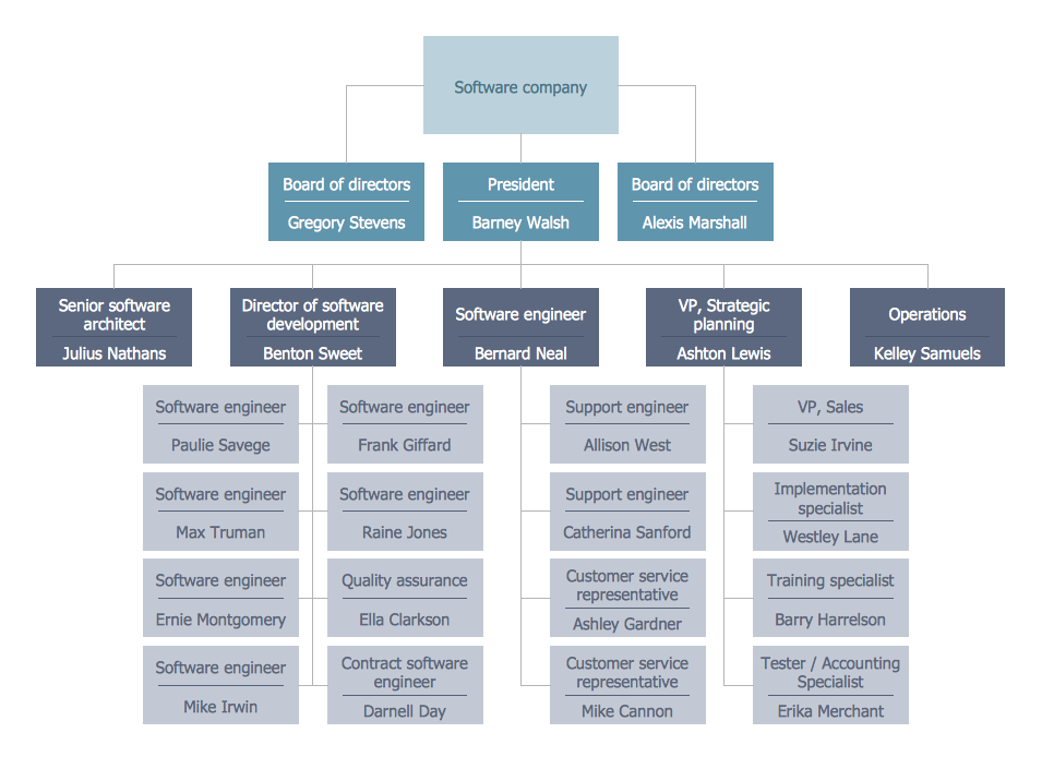
Picture: Business Structure
Related Solution:
The 7 Management and Planning Tools solution implements well-known methodologies for problem analysis and solving. Different products from the ConceptDraw Office suite can be used as a complete solution for any of the methodologies in this solution. ConceptDraw Office provides visual communication during every stage of work.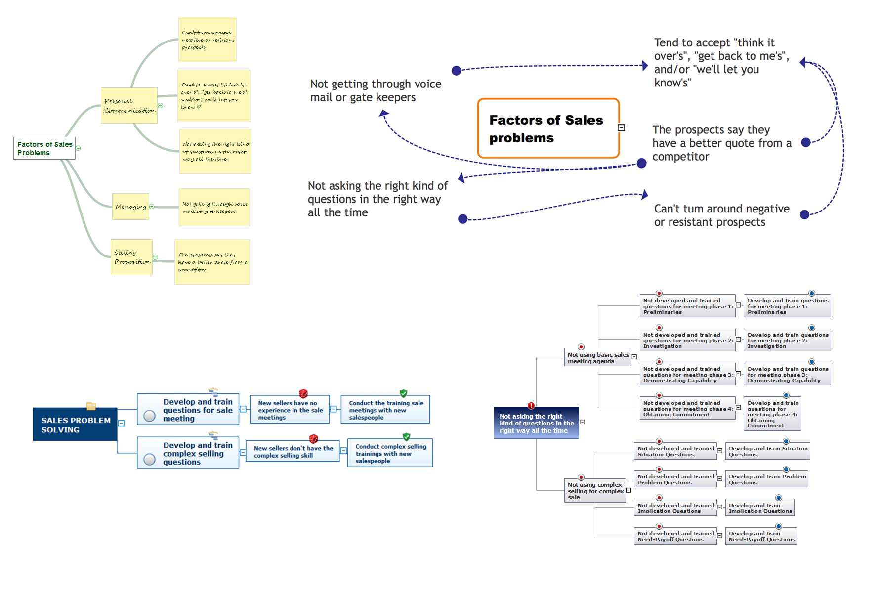
Picture: 7 Management & Planning Tools
Related Solution:
This pyramid chart example is supplied with the ConceptDraw Pyramid Diagrams solution. This is a model of Information Management Systems classification. It is made in a form of a four-level pyramid. The top level shows the information system developed for an executive management. Below, there is a level depicting the system of decision making process for the managers of the senior level. A schematic representation of the middle management information system, following to logic, is in the middle of the pyramid. And at least, the lowermost level represents an information processing system for employees.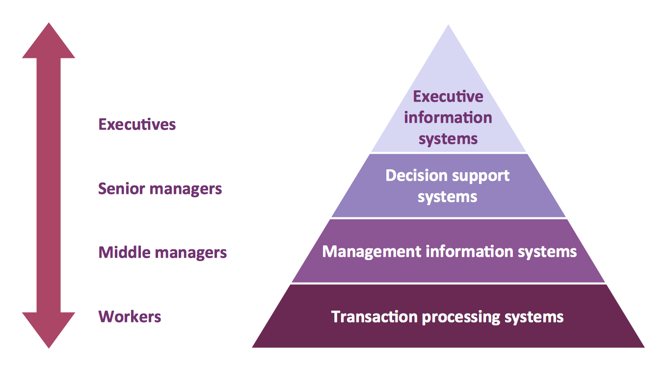
Picture: Pyramid Diagram
Related Solutions:
ConceptDraw DIAGRAM software extended with Fishbone Diagrams solution from the Management area of ConceptDraw Solution Park is perfect for Cause and Effect Diagram creating. It gives the ability to draw fishbone diagram that identifies many possible causes for an effect or a problem. Causes and Effects are usually grouped into major categories to identify these sources of variation. Causes and Effects in the diagram show relationships among various factor. Fishbone diagram shows factors of Equipment, Process, People, Materials, Environment and Management, all affecting the overall problem.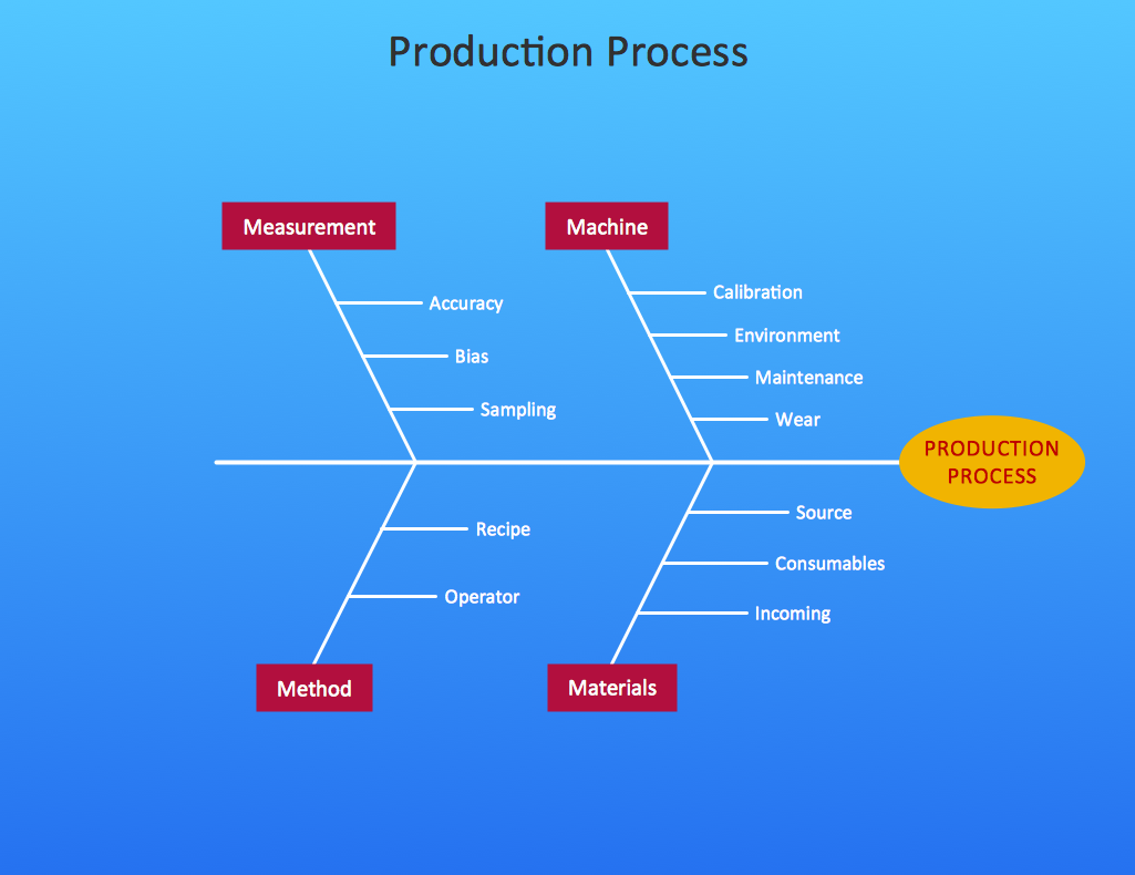
Picture: Cause and Effect Diagram
Related Solution:
Have you ever wanted to start your own cafe? To imagine any possible options, try Cafe Floor Plan Design Software now for free 21 day trial. This will allow you to use all the ConceptDraw DIAGRAM main features.
Here is an example of a multi-page document consisting from the various options of interior design and plans for arranging a cafe. This document can be used as a basis for the development of a professional designer portfolio. It was drawn using ConceptDraw Cafe and Restaurant Plans solution. The solution supplies vector libraries, templates and samples that are released to assist amateurs and professionals to draw the i designs of interior and furniture layouts of the cafe hall and lobby.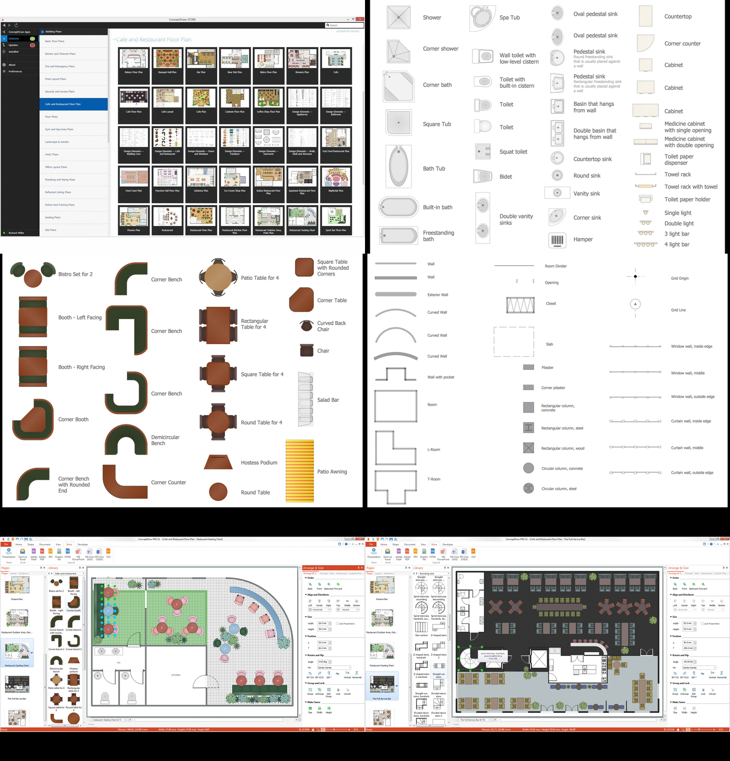
Picture: How to create Cafe Floor Plan Design
Related Solution: