The Best Mac Software for Diagramming or Drawing
What is the Tool for Drawing Diagrams in Mac?
Do you need to make an amazing flowchart on your Mac? Diagram? Looking for the best MS Visio software, which you can use on your Mac, you can simply go for ConceptDraw DIAGRAM application, ensuring yourself in getting even better results of your drawing using it. The reason for ConceptDraw DIAGRAM software to be that popular is the solutions, developed for its users to have in order to create only professionally looking charts, flowcharts, diagrams, schemes, plans and maps. The pre-made examples and templates as well as the design elements from the stencil libraries of such solutions are meant to help you to make smart looking drawings within a very short period of time getting the needed result having all the necessary tools in only a few hours or even minutes, depending how good and familiar you are with the mentioned software.
Example 1. The Best Mac Software for Diagramming or Drawing
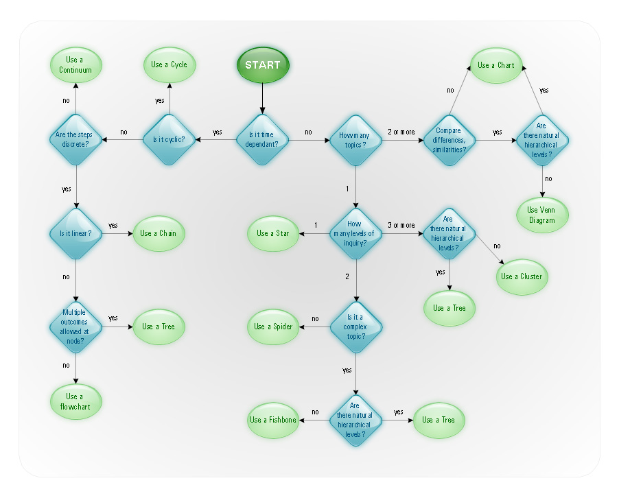
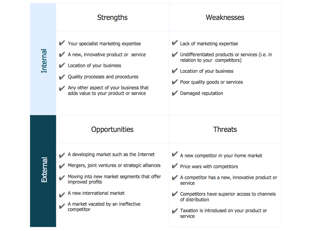
In order to draw your business communication ideas and concepts, the simple visual presentations of some numerical data, illustrating this data in a way of schematics is always better with the best diagrams drawing software – Concept Draw PRO. The list of the diagrams, which can be created with help of this tool is almost endless: flowcharts, block diagrams, bar charts, histograms, pie charts, divided bar diagrams, line graphs, area charts, scatter plots, circular arrows diagrams, Venn diagrams, bubble diagrams, concept maps and many other diagrams can be all made using ConceptDraw DIAGRAM block diagrams, line graphs, area charts and many more other charts and flowcharts diagramming software.

Example 2. The Best Mac Software for Diagramming or Drawing
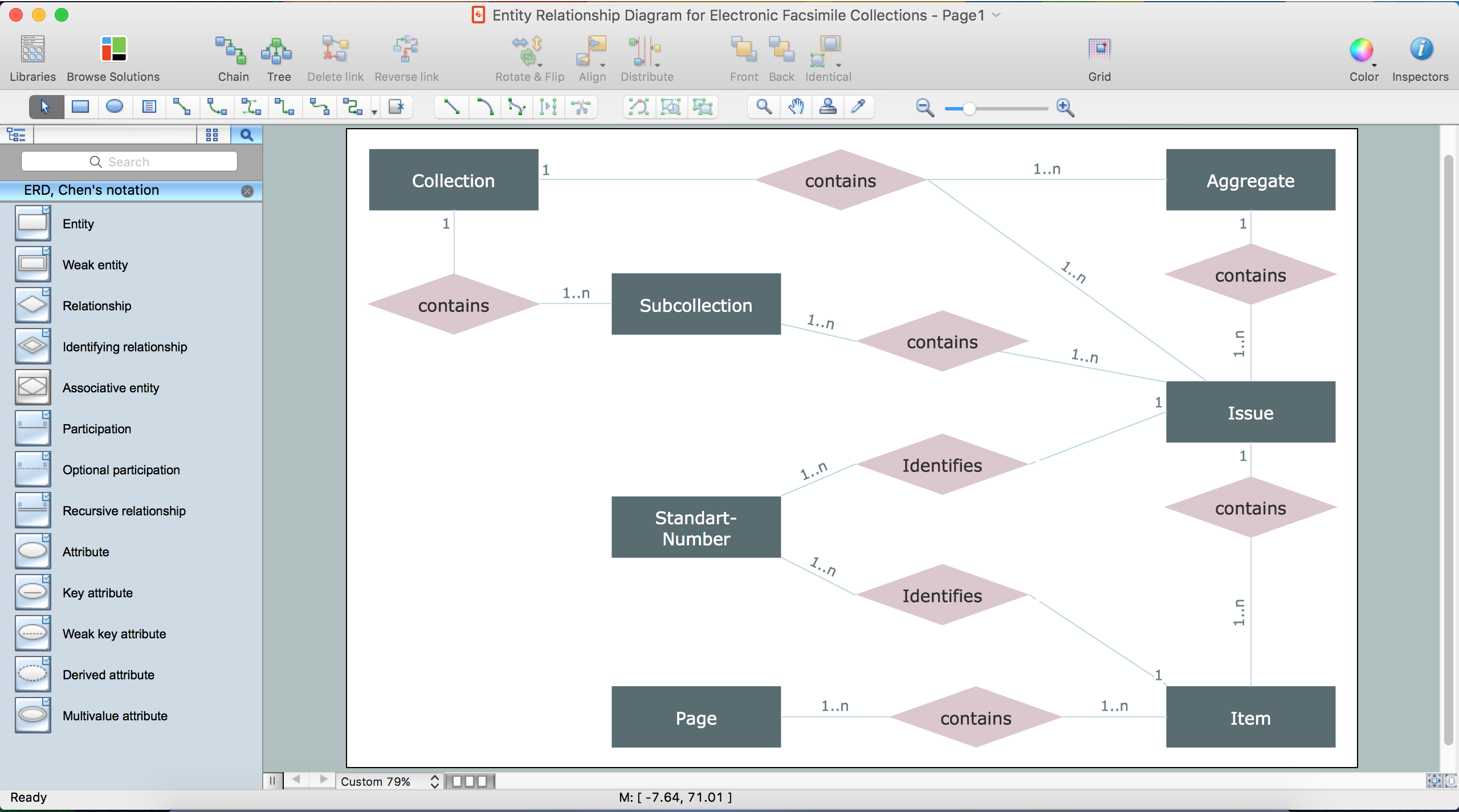
As an example of what can be created with help of ConceptDraw DIAGRAM application, we want to mention the ER- diagram, which is well known and commonly used Entity-Relationship Diagram. The components for drawing such ER diagram are all there in our stencil libraries of the “Entity-Relationship Diagram (ERD) Solution”, and being an experienced user of ConceptDraw DIAGRAM will take you only about 10 or 15 minutes to create any ERD using the provided samples. Once you are not as experienced with the mentioned software, then it may take a little bit longer for the first time, but still our pre-made samples and templates will be very useful for you, simplifying your work of creating the needed diagrams. Thus, the Entity-Relationship Diagram (ERD) Solution for ConceptDraw DIAGRAM allows you to create your own Entity-Relationship Diagrams of any complexity quickly, simply and effectively.
The mentioned Entity-Relationship Diagram (ERD) solution can be found and downloaded from ConceptDraw STORE application, extending the ConceptDraw DIAGRAM ector graphics and diagramming software with the ability of drawing your own entity-relationship diagrams using both Chen's or/and Crow's Foot notations, offering two stencil libraries with numerous pre-designed ER-icons, which are “ERD, Chen's Notation” and “ERD, Crow's Foot Notation” libraries.

Example 3. ERD Diagrams in MS Visio and ConceptDraw
Data flow diagram is also a very well-known as well as commonly used representation of data, with help of which you can represent any data flow in a system. Data Flow Diagrams (DFD) are a great part of the Structured Systems Analysis and Design Methodology, being consisted of so many different components, such as processes and functions, representing the actions happened in information system. There are the external entities mentioned within this drawing, which represent the data ingoing to and outgoing from in the system. The illustrated data depositories on the mentioned diagram represent places in the system, where data can be saved for a definite period of time and the represented data flows indicate the directions as well as a character of data, flowing within the considered information system.
The main data flow diagram elements are: processes, data flow, external entities and data store. So called “Yourdon — de Marco notation” is the one, being widely used for representation of the Data Flow Diagram objects. The design objects, which can be used for creating the Data Flow Diagrams, can be interpreted in a way of processes transforming the input data flows into the output data flows. Such design objects all can be found in the Data Flow Diagrams Solution to be very useful for those who intend to make great looking, professionally as well as smart looking data flow diagrams while working in ConceptDraw DIAGRAM data flow diagramming software.

Example 4. DFD Diagram in MS Visio and ConceptDraw
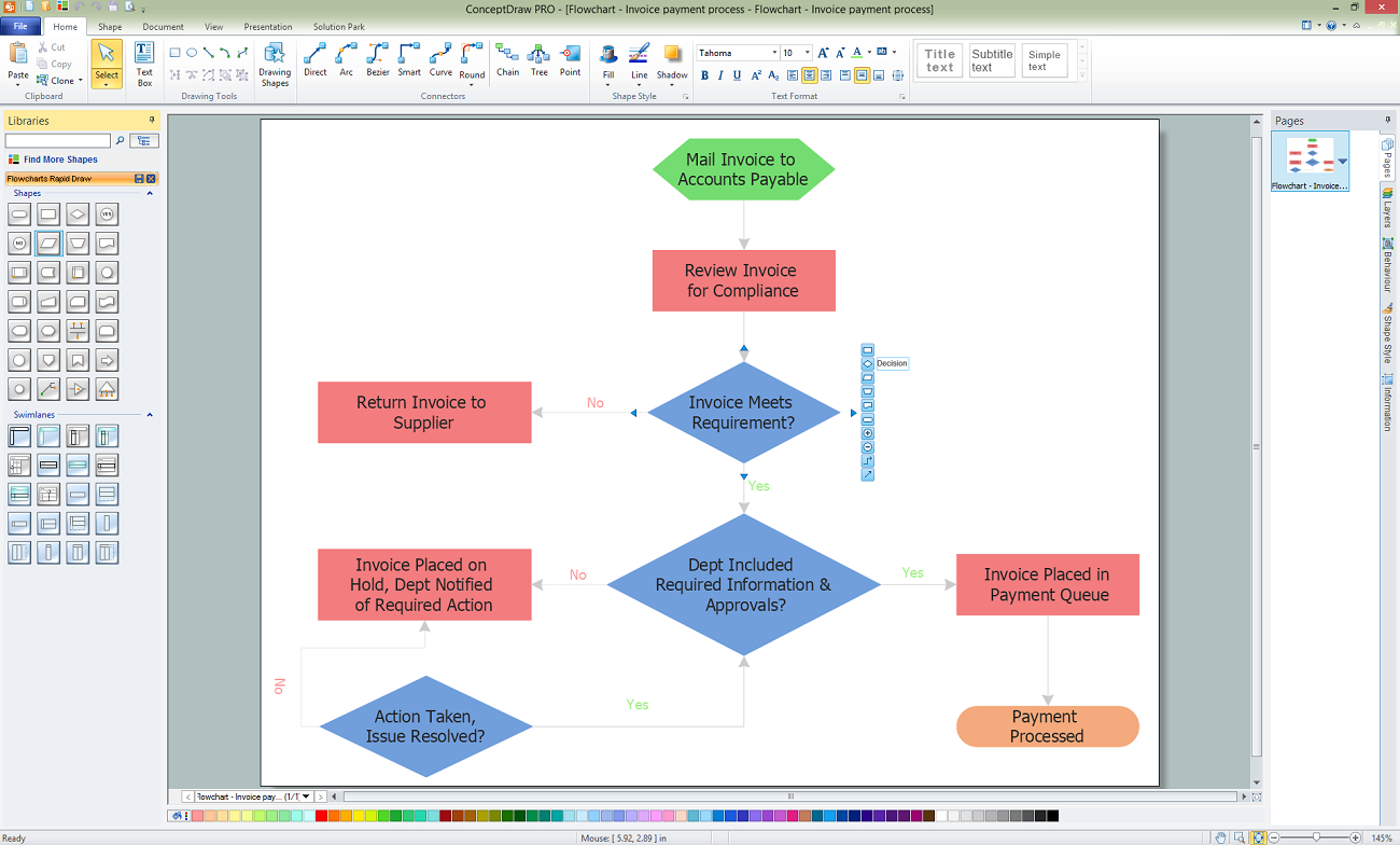
Apart from the diagrams, there are also very many different types of flowcharts which also can be created within the best flowcharts and diagrams drawing software — ConceptDraw DIAGRAM Thus, the Basic Flowchart, which is often being used for defining as well as documenting the basic work and data flows in production, quality and financial management processes in order to increase the efficiency of so many different spheres of business activity, can be simply created in ConceptDraw DIAGRAM basic flowchart software suing the Flowchart solution.
The Business Process Modelling Diagram is a simple graphical representation, used for specifying the numerous business processes in a workflow as well as the Process Flowchart (also known as the “system flow diagram” or “SFD”), used to show the relationships between the major parts of the system, can be made with the existing tools, which ConceptDraw STORE, as another CS Odessa product, provides in its Solutions.
Another type of diagrams that can be made in the best flowchart maker — ConceptDraw DIAGRAM — is a Process Flow one, which presents a range of symbols representing different appliances. It can be created with all provided necessary design symbols as well as design elements from the stencil libraries from Solutions, depending on what exactly you need to create and in what way it should look like. The mentioned design elements are meant to be used for making many different flowcharts and diagrams, including the “Cross Functional Flowchart”, which is often used to show the relationship between some business processes as well as the functional units (such as units or departments responsible for such business processes to be managed in an appropriate way).