Guesthouse Network. WIFI network to my guest house

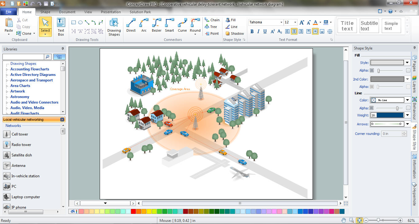
This sample was created in ConceptDraw DIAGRAM diagramming and vector drawing software using the Computer and Networks solution from Computer and Networks area of ConceptDraw Solution Park.
Electrical Symbols — VHF UHF SHF

26 libraries of the Electrical Engineering Solution of ConceptDraw DIAGRAM make your electrical diagramming simple, efficient, and effective. You can simply and quickly drop the ready-to-use objects from libraries into your document to create the electrical diagram.
Network Engineering
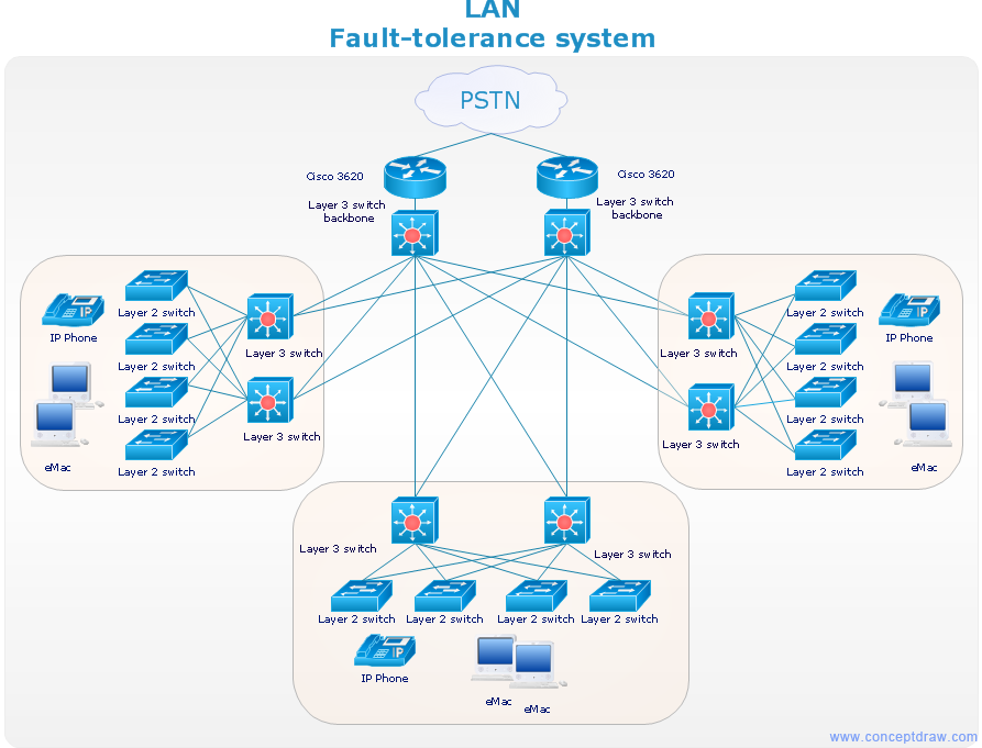
Hotel Network Topology Diagram

Use it to draw the physical and logical network topology diagrams for wired and wireless computer communication networks.

Network Diagram Software. LAN Network Diagrams. Physical Office Network Diagrams


Metropolitan area networks (MAN). Computer and Network Examples
. Computer and Network Examples")
Electrical Symbols — Qualifying

26 libraries of the Electrical Engineering Solution of ConceptDraw DIAGRAM make your electrical diagramming simple, efficient, and effective. You can simply and quickly drop the ready-to-use objects from libraries into your document to create the electrical diagram.
Star Network Topology

Use it to draw the physical and logical network topology diagrams for wired and wireless computer communication networks.
Electrical Symbols — Transmission Paths
26 libraries of the Electrical Engineering Solution of ConceptDraw DIAGRAM make your electrical diagramming simple, efficient, and effective. You can simply and quickly drop the ready-to-use objects from libraries into your document to create the electrical diagram.
Network Diagrams for Bandwidth Management
Use Computer & Networks solution to draw the network diagrams for bandwidth management for Cisco networks, Apple networks, IVR networks, GPRS networks, wi-fi networks, LAN and WAN.
- Download Report On Internal Circuit Diagram Of Wifi Router
- How To Make Room Hotspot Wifi Circuit Diagram
- Circuit Diagram Of A Wifi Hotspot
- Network Hubs | Network Protocols | Schematic For Wifi Router
- 3d Circuit Diagram Of Wifi Router
- Free Wifi Netwark Circuit Diagram
- Cisco Wifi Router Circuit Diagram
- Cricuit Diagram In Wifi
- IVR network - Vector stencils library | Wifi Khotspot Diagram
- Wifi Router System Schematic
- ERD | Entity Relationship Diagrams, ERD Software for Mac and Win
- Flowchart | Basic Flowchart Symbols and Meaning
- Flowchart | Flowchart Design - Symbols, Shapes, Stencils and Icons
- Flowchart | Flow Chart Symbols
- Electrical | Electrical Drawing - Wiring and Circuits Schematics
- Flowchart | Common Flowchart Symbols
- Flowchart | Common Flowchart Symbols