 Chemical and Process Engineering
This chemical engineering solution extends ConceptDraw DIAGRAM.9.5 (or later) with process flow diagram symbols, samples, process diagrams templates and libraries of design elements for creating process and instrumentation diagrams, block flow diagrams (BFD
Process Flow Diagram Symbols

HelpDesk
How to Draw a Process Flow Diagram

HelpDesk
How to Draw a Chemical Process Flow Diagram

Business Board Org Chart

This sample shows the organizational chart in the field of Architect Engineering. Create your own orgchart professional drawings using ConceptDraw.
Databases Access Objects Model with ConceptDraw DIAGRAM

Model Based Systems Engineering

Create Organizational Chart

ConceptDraw DIAGRAM organizational chart professional software allows quickly create organizational charts, flow charts, time lines, and much more. Use it for drawing organizational chart for any size company and analyzing organizational structure. Use ConceptDraw to create organizational chart, visualize company Organizational chart, hospital Organizational chart, hotel Organizational chart, corporate organizational chart, etc.
 SYSML
SYSML
The SysML solution helps to present diagrams using Systems Modeling Language; a perfect tool for system engineering.


This circle-spoke diagram sample shows the social determinants of health. It was created on the base of the hub-and-spoke diagram from the Health Canada website. [hc-sc.gc.ca/ sr-sr/ pubs/ hpr-rpms/ bull/ 2005-climat/ 2005-climat-6-eng.php]
"Social determinants of health are the economic and social conditions – and their distribution among the population – that influence individual and group differences in health status. They are risk factors found in one's living and working conditions (such as the distribution of income, wealth, influence, and power), rather than individual factors (such as behavioural risk factors or genetics) that influence the risk for a disease, or vulnerability to disease or injury. According to some viewpoints, these distributions of social determinants are shaped by public policies that reflect the influence of prevailing political ideologies of those governing a jurisdiction. ...
In 2003, the World Health Organization (WHO) Europe suggested that the social determinants of health included:
(1) Social gradients (life expectancy is shorter and disease is more common further down the social ladder).
(2) Stress (including stress in the workplace).
(3) Early childhood development.
(4) Social exclusion.
(5) Unemployment.
(6) Social support networks.
(7) Addiction.
(8) Availability of healthy food.
(9) Availability of healthy transportation." [Social determinants of health. Wikipedia]
The hub-and-spoke diagram example "Social determinants of health" was created using the ConceptDraw PRO diagramming and vector drawing software extended with the Circle-Spoke Diagrams solution from the area "What is a Diagram" of ConceptDraw Solution Park.
Circle-spoke diagram

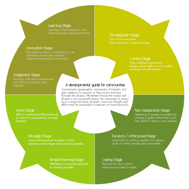
This ring chart sample was created on the base of the figure illustrating the "CCP Handbook - Comprehensive Community Planning for First Nations in British Columbia" from the Government of Canada website. "Tool 1: Centre for Innovative & Entrepreneurial Leadership (CIEL) Community Life Cycle Matrix.
Actualization Phase.
Community is highly developed and encourages learning & innovation while respecting history and culture. Community shares resources with others and regularly monitors itself, continuing to enhance capacity.
Action: Community undertakes regular reviews and reflection activities to maintain or enhance stage / phase.
Pre-Community or Chaos Phase.
Community is undeveloped. Limited sharing of resources or recognition of value of a community.
Action: Community can (re)form through the identification of and action of influential and respected leaders (elected or unelected).
Vision Phase.
Community recognizes the importance of vision and long-term planning; is able to move in this direction.
Action: Community can engage in planning, meaningful consultation of its members, & working towards the development of strategic thinking & planning, and, ultimately, identifying community-wide values, distinct community characteristics and a vision.
Emergence Phase.
Community exists but has significant problems, making anything but survival & fulfilling short-term needs impossible.
Action: Community can advance through focus on small, non-political, trustbuilding projects to build success, respect, confidence, relationships & skills.
Why the Matrix.
The challenge of developing innovative and entrepreneurial communities is in ensuring that the communities have a clear picture of where they are at and where they want to go. This enables a better match of the tools available with both the capacity of the community and the hoped for goal. For example, while strategic planning may work for some communities, the planning process may also lead to frustration and failure in other communities that do not have the necessary trust, social capital or capacity." [aadnc-aandc.gc.ca/ eng/ 1100100021972/ 1100100022090]
The ring chart example "Community life cycle matrix" was created using the ConceptDraw PRO diagramming and vector drawing software extended with the Target and Circular Diagrams solution from the Marketing area of ConceptDraw Solution Park.
www.conceptdraw.com/ solution-park/ marketing-target-and-circular-diagrams
Ring chart
Ice Hockey Diagram — Defensive Strategy — Neutral Zone Trap

SysML

ConceptDraw DIAGRAM diagramming and vector drawing software was extended with SysML Solution from the Software Development Area of ConceptDraw Solution Park specially to help systems engineers design various model systems with SysML.
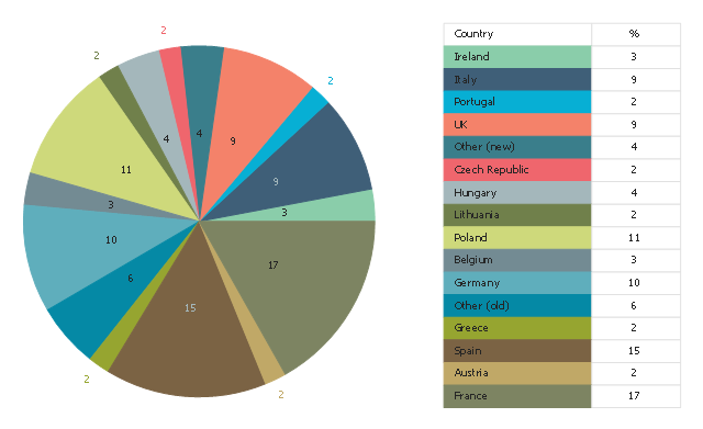
This pie chart sample shows the percentage of EU farm land by country. It was designed on the base of the Wikimedia Commons file: EUFarm-eng.svg. [commons.wikimedia.org/ wiki/ File:EUFarm-eng.svg]
"The agricultural sector is supported by subsidies from the European Union in the form of the Common Agricultural Policy (CAP). In 2013 this represented approximately €45billion (less than 33% of the overall budget of €148billion) of the EU's total spending. It was used originally to guarantee a minimum price for farmers in the EU. This is criticised as a form of protectionism, inhibiting trade, and damaging developing countries; one of the most vocal opponents is the UK, the second largest economy within the bloc, which has repeatedly refused to give up the annual UK rebate unless the CAP undergoes significant reform; France, the biggest beneficiary of the CAP and the bloc's third largest economy, is its most vocal proponent." [Economy of the European Union. Wikipedia]
The pie chart example "Percentage of EU farm land by country" was created using the ConceptDraw PRO diagramming and vector drawing software extended with the Pie Charts solutiton of the Graphs and Charts area in ConceptDraw Solution Park.
Pie chart
The vector stencils library "Dimensioning and tolerancing" contains 45 symbols of geometric dimensions and mechanical tolerances, geometric symbols, callouts, and text boxes and inserts.
Use these geometric dimensioning and tolerancing (GD&T) shapes to create annotated mechanical drawings in the ConceptDraw PRO diagramming and vector drawing software extended with the Mechanical Engineering solution from the Engineering area of ConceptDraw Solution Park.
www.conceptdraw.com/ solution-park/ engineering-mechanical
Datum (old)
-dimensioning-and-tolerancing---vector-stencils-library.png--diagram-flowchart-example.png)
Box callout

Datum symbol

Callout

All around callout

Text block

2 datum frame

Simple frame

Basic frame

1 datum frame

3 datum frame

Straightness

Flatness

Line profile

Circularity

Cylindricity

Surface profile

Position

Concentricity

Symmetry

Parallelism

Perpendicularity

Angularity

Material condition

Arc length

Diameter

Counterbore/ spotface

Countersink

Depth

Slope

Conical taper

Statistical tolerance

Datum (new)
-dimensioning-and-tolerancing---vector-stencils-library.png--diagram-flowchart-example.png)
Datum (new) 2
-2-dimensioning-and-tolerancing---vector-stencils-library.png--diagram-flowchart-example.png)
Target point

Target line

Target area (circle)
-dimensioning-and-tolerancing---vector-stencils-library.png--diagram-flowchart-example.png)
Target area (rectangle)
-dimensioning-and-tolerancing---vector-stencils-library.png--diagram-flowchart-example.png)
Total runout

Total runout 2

Circular runout

Circular runout 2

Surface finish

Surface finish, removal process

Surface finish, no process permitted

The vector stencils library "Telecommunication networks" contains 32 clipart images of telecommunication network devices and equipment for drawing telecom network diagrams.
"A telecommunications network is a collection of terminal nodes, links and any intermediate nodes which are connected so as to enable telecommunication between the terminals.
The transmission links connect the nodes together. The nodes use circuit switching, message switching or packet switching to pass the signal through the correct links and nodes to reach the correct destination terminal.
Each terminal in the network usually has a unique address so messages or connections can be routed to the correct recipients. The collection of addresses in the network is called the address space." [Telecommunications network. Wikipedia]
The clip art example "Telecommunication networks - Vector stencils library" was created using the ConceptDraw PRO diagramming and vector drawing software extended with the Telecommunication Network Diagrams solution from the Computer and Networks area of ConceptDraw Solution Park.
Internet

Globe

Base station

Satellite dish

Satellite dish

Communications satellite

Wireless cell tower

Radio waves

Radio waves

Cellular phone

Server

Laptop computer

Desktop computer

Car

Satellite truck

House

House

Office building

Mountain

Tree

Tree

User

Call-center

Multi-storey

Antenna

Router

IP phone

Fax

Network cell

IP Camera

Wireless router

Networking device

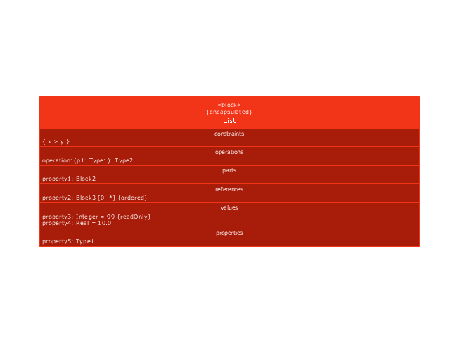
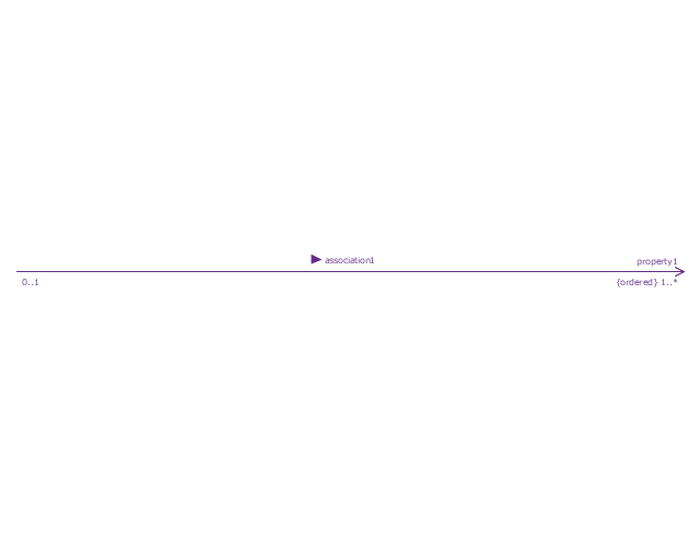
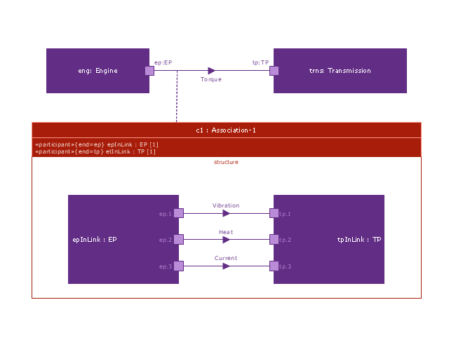
This vector stencils library contains 54 BDD symbols.
Use it to design your block definition diagrams using ConceptDraw PRO diagramming and vector drawing software.
"Block Definition Diagram
A block definition diagram is based on the UML class diagram, with restrictions and extensions as defined by SysML. ...
Block and ValueType Definitions
A SysML Block defines a collection of features to describe a system or other element of interest. A SysML ValueType
defines values that may be used within a model. SysML blocks are based on UML classes, as extended by UML composite structures. SysML value types are based on UML data types. Diagram extensions for SysML blocks and value types are described by other subheadings of this sub clause." [www.omg.org/ spec/ SysML/ 1.3/ PDF]
The vector stencils library "Block definition diagram" is included in the SysML solution from the Software Development area of ConceptDraw Solution Park.
Block definition diagram
Block
Actor

Actor 2

Value type

Enumeration

Abstract definition

Abstract definition 2
Abstract definition 3
Stereotype property compartment

Namespace compartment
Structure compartment
Unit

Unit 2

Quantity kind

Instance specification
Instance specification 2

Instance specification 3

Instance specification 4
Dependency
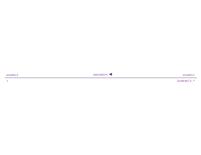
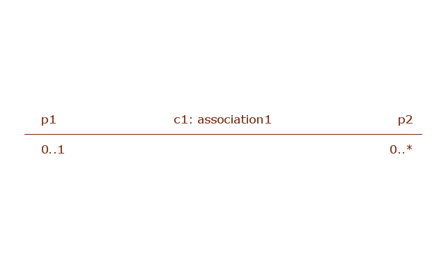
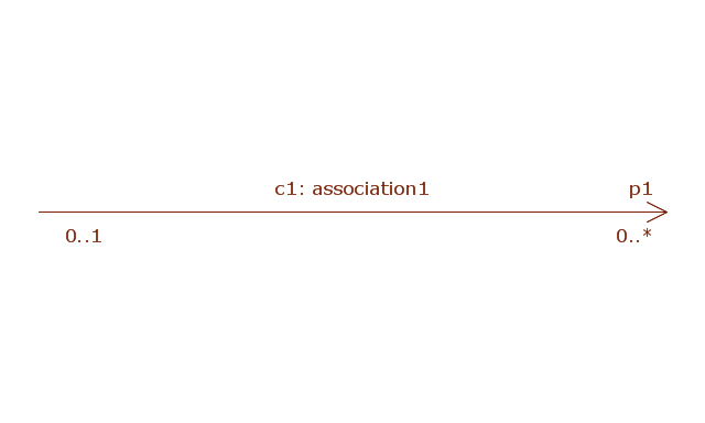
Reference association
Reference association 2
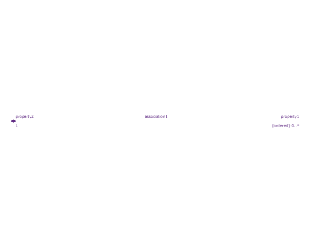
Part association
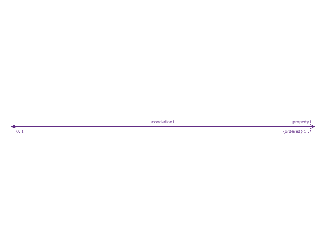
Part association 2
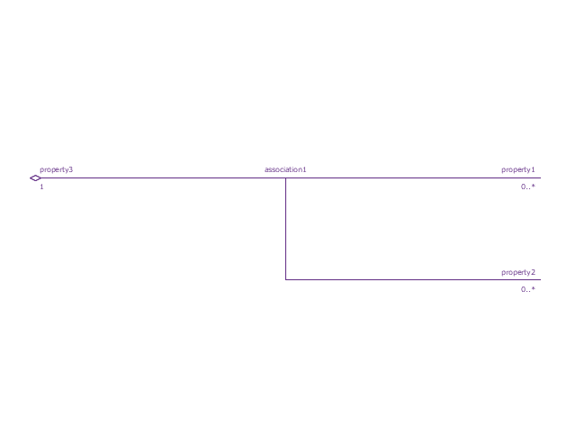
Shared association
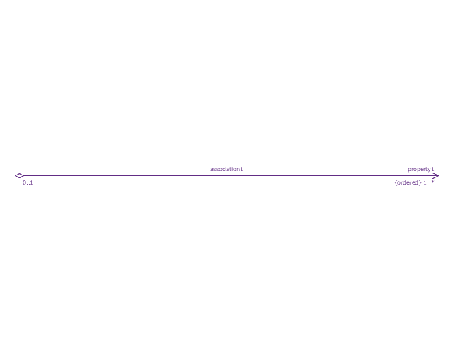
Shared association 2

Multibranch part association
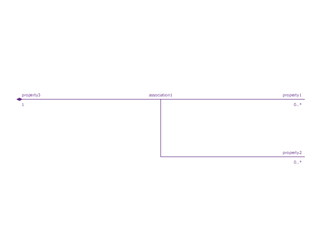
Multibranch shared association
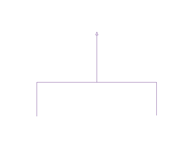
Generalization

Multibranch generalization
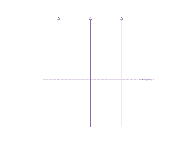
Generalization set, disjoint
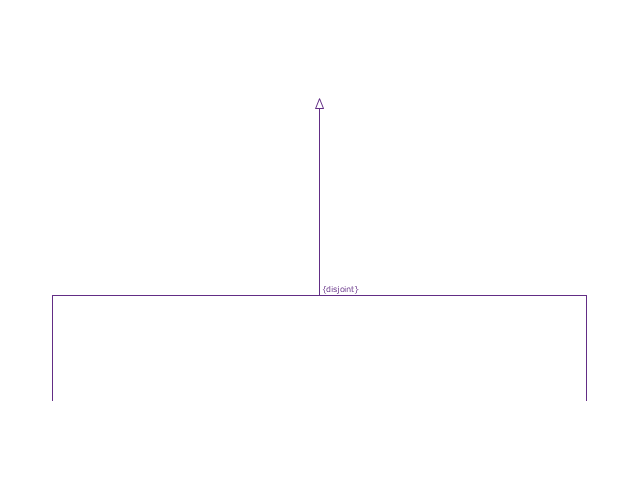
Generalization set, overlapping
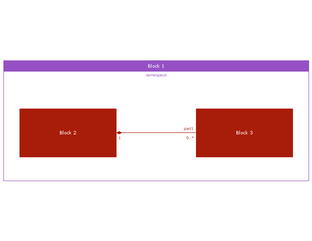
Block namespace containment

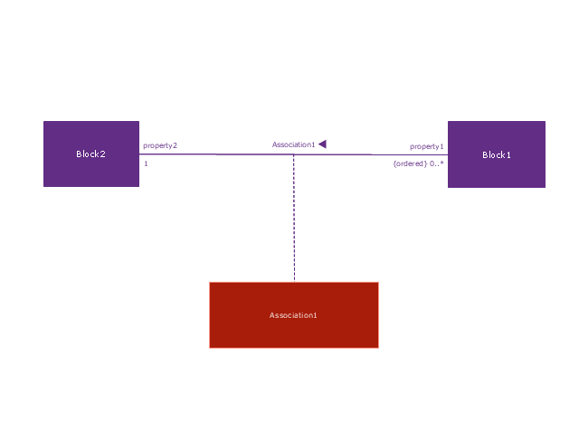
Participant property
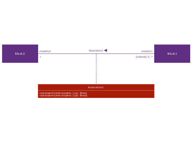
Participant property 2
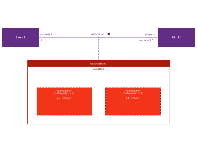
Participant property 3
Connector property
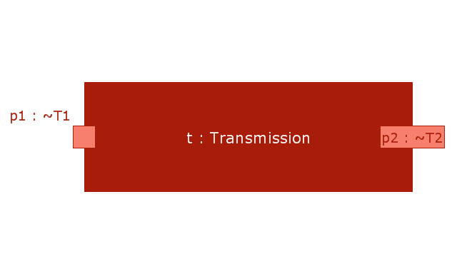
Conjugated ports

Conjugated ports 2

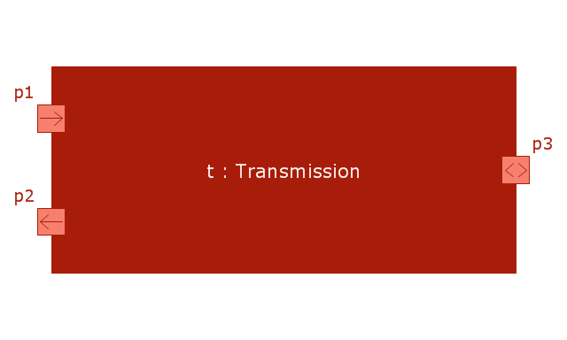
Ports with flow properties

Port (compartment notation)
-vector-stencils-library---block-definition-diagram.png--diagram-flowchart-example.png)
Port (nested)
-vector-stencils-library---block-definition-diagram.png--diagram-flowchart-example.png)
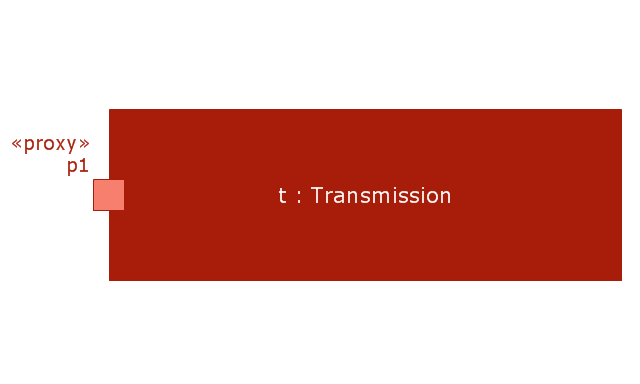
Proxy port
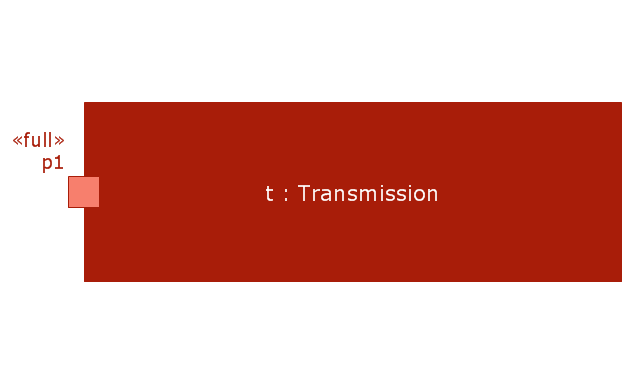
Full port

Flow property
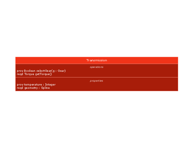
Required and provided features
Interface block

Item flow
Item flow 2
Item flow 3
Interface

Required and provided interfaces

Required and provided interfaces 2
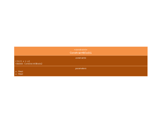
Constraint block
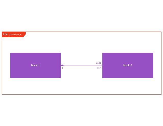
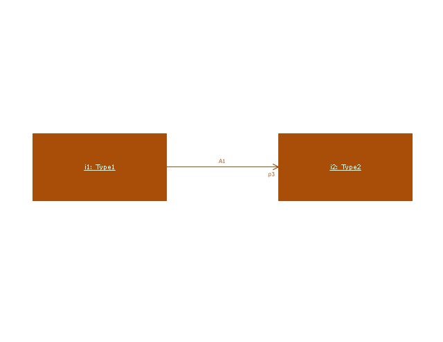
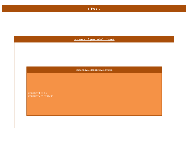
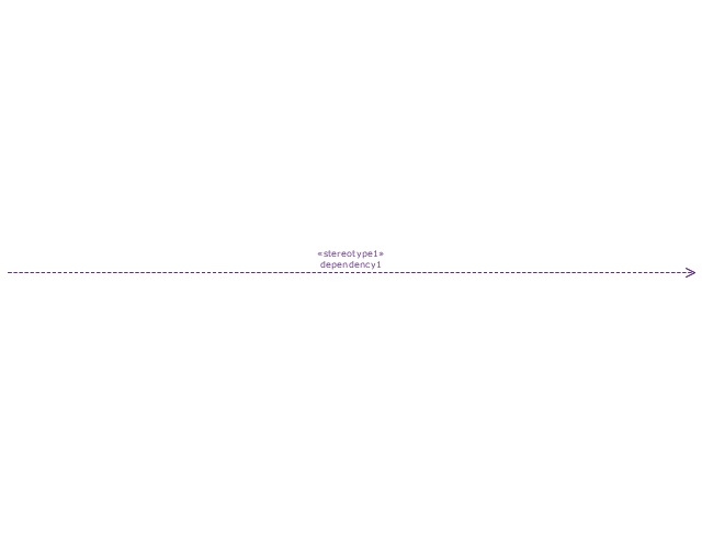
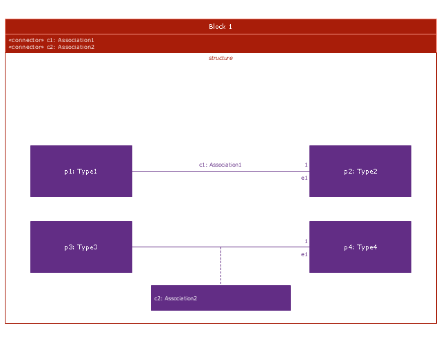
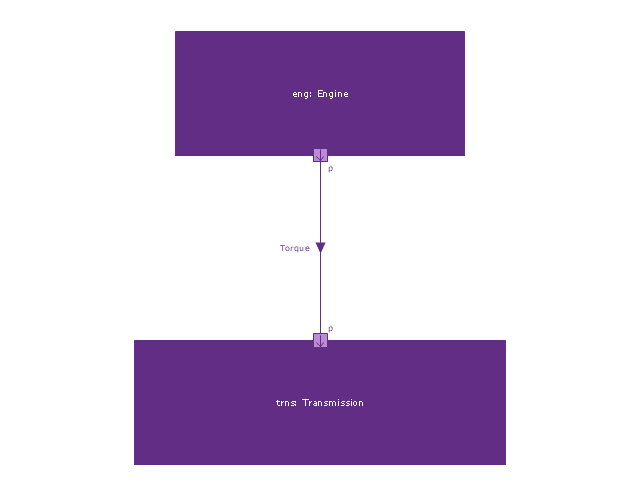
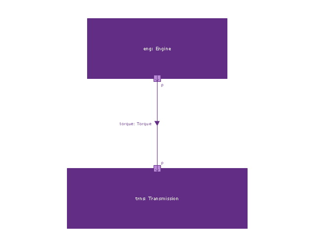
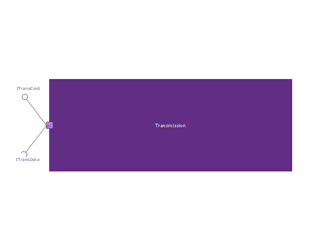
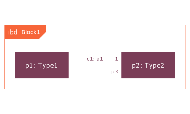
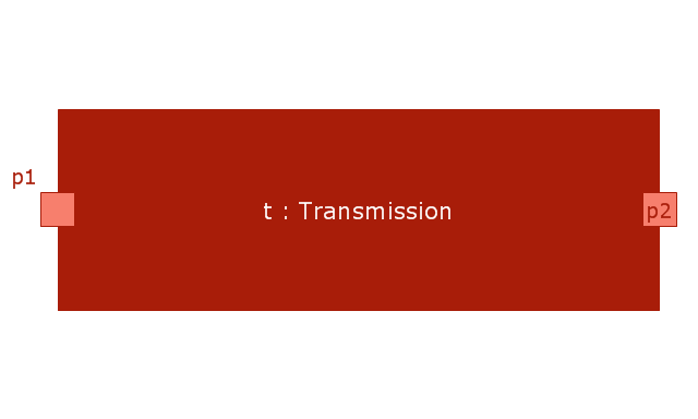
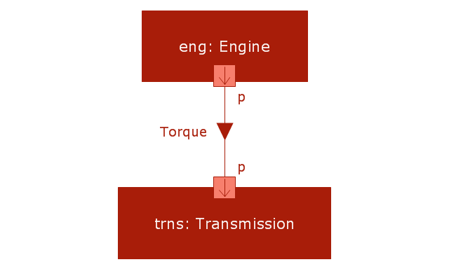
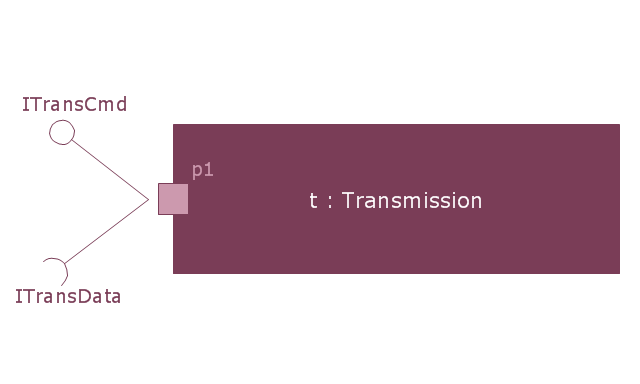
This vector stencils library contains 22 IBD symbols.
Use it to design your internal block diagrams using ConceptDraw PRO diagramming and vector drawing software.
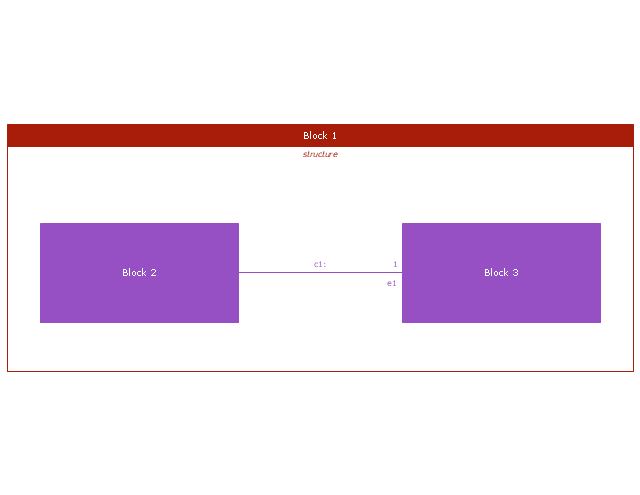
"Internal Block Diagram
An internal block diagram is based on the UML composite structure diagram, with restrictions and extensions as defined
by SysML. ...
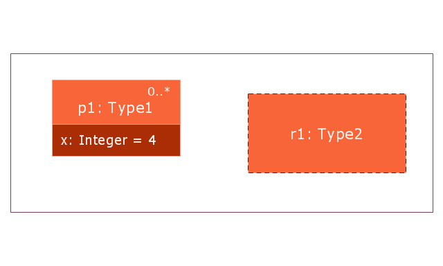
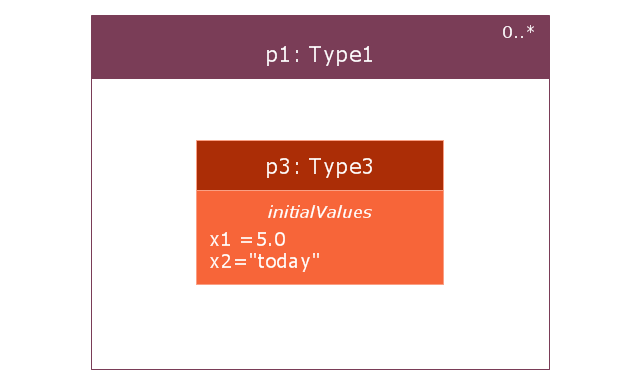
Property types
Four general categories of properties of blocks are recognized in SysML: parts, references, value properties, and
constraint properties. ... A part or value property is always shown on an internal block diagram with a solid-outline box. A reference property is shown by a dashed-outline box, consistent with UML. Ports are special cases of properties, and have a variety of notations... Constraint properties and their parameters also have their own notations... " [www.omg.org/ spec/ SysML/ 1.3/ PDF]
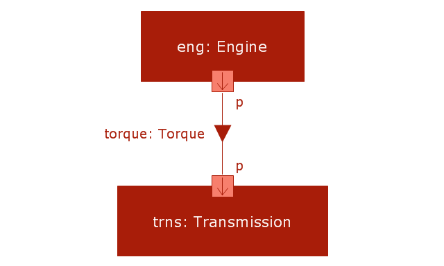
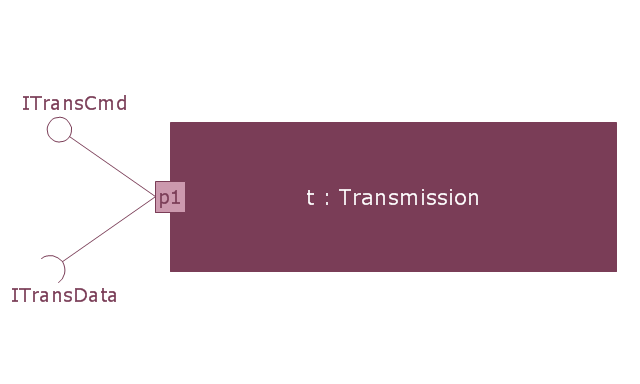
The vector stencils library "Internal block diagram" is included in the SysML solution from the Software Development area of ConceptDraw Solution Park.
Use it to design your internal block diagrams using ConceptDraw PRO diagramming and vector drawing software.
"Internal Block Diagram
An internal block diagram is based on the UML composite structure diagram, with restrictions and extensions as defined
by SysML. ...
Property types
Four general categories of properties of blocks are recognized in SysML: parts, references, value properties, and
constraint properties. ... A part or value property is always shown on an internal block diagram with a solid-outline box. A reference property is shown by a dashed-outline box, consistent with UML. Ports are special cases of properties, and have a variety of notations... Constraint properties and their parameters also have their own notations... " [www.omg.org/ spec/ SysML/ 1.3/ PDF]
The vector stencils library "Internal block diagram" is included in the SysML solution from the Software Development area of ConceptDraw Solution Park.
Internal block diagram
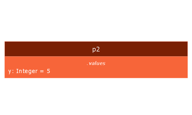
Property
Property 2
Actor part
Actor part 2

Property specific type
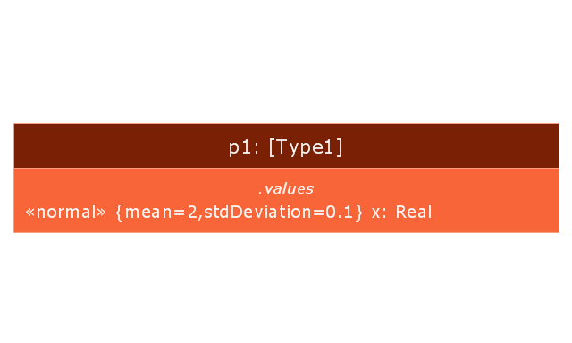
Property specific type 2
Dependency
Binding connector

Binding connector, equal
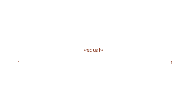
Bidirectional connector
Unidirectional connector
Conjugated ports
Conjugated ports 2
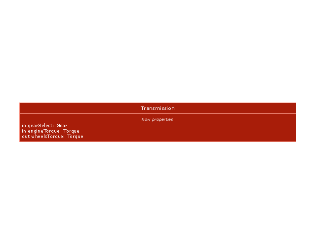
Ports with flow properties
Port (nested)
-vector-stencils-library---internal-block-diagram.png--diagram-flowchart-example.png)
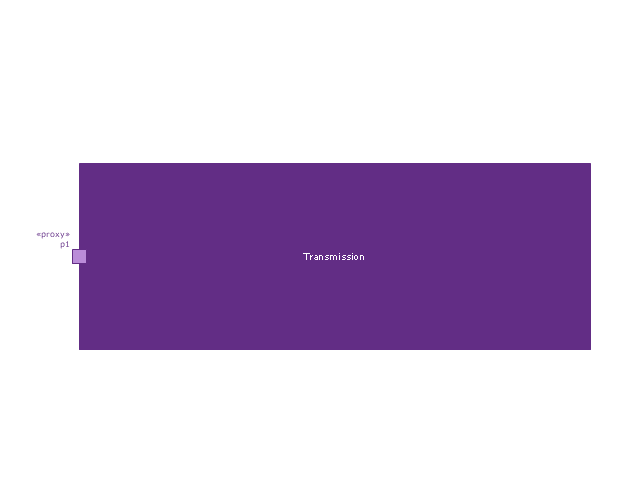
Proxy port
Full port
Item flow
Item flow with an item property
Required and provided interfaces
Required and provided interfaces 2
This engineering drawing present weld type symbols and fillet weld symbols.
The weld type symbol is typically placed above or below the center of the reference line, depending on which side of the joint it's on. The symbol is interpreted as a simplified cross-section of the weld.
"Fillet welding refers to the process of joining two pieces of metal together whether they be perpendicular or at an angle. These welds are commonly referred to as Tee joints which are two pieces of metal perpendicular to each other or Lap joints which are two pieces of metal that overlap and are welded at the edges. The weld is aesthetically triangular in shape and may have a concave, flat or convex surface depending on the welder’s technique. Welders use fillet welds when connecting flanges to pipes, welding cross sections of infrastructure, and when fastening metal by bolts isn't strong enough." [Fillet weld. Wikipedia]
The engineering drawing example Welding symbols is included in the Mechanical Engineering solution from Engineering area of ConceptDraw Solution Park.
Welding joint symbols

- How to Draw a Chemical Process Flow Diagram | Design elements ...
- Chemical Engineering | Chemical and Process Engineering ...
- Chemical and Process Engineering | Technical Drawing Software ...
- Chemical Engineering | Process Flow Diagram Symbols | Technical ...
- Process Flow Diagram Symbols | Chemical Engineering | Chemical ...
- Technical Drawing Electrical Engineering
- How to Draw a Chemical Process Flow Diagram
- Software development with ConceptDraw DIAGRAM | Data Flow ...
- Mechanical Engineering | ConceptDraw Solution Park | Stakeholder ...
- Home Electrical Plan | Electrical Symbols, Electrical Diagram ...
- Chemical and Process Engineering | Chemical Engineering ...
- Examples of Reed-Kellogg diagrams | The Reed-Kellogg system ...
- Software development with ConceptDraw DIAGRAM | Conventional ...
- Mechanical Drawing Symbols | Mechanical Engineering | Process ...
- Mechanical Engineering Diagram Pdf Download
- Electrical Symbols, Electrical Diagram Symbols | Electrical Drawing ...
- Mechanical Engineering | Mechanical Drawing Symbols | Process ...
- Mechanical Drawing Symbols | Mechanical Engineering | Process ...
- Mechanical Drawing Symbols | Mechanical Engineering ...
- Mechanical Engineering | Floor Plans | Chemical and Process ...
- ERD | Entity Relationship Diagrams, ERD Software for Mac and Win
- Flowchart | Basic Flowchart Symbols and Meaning
- Flowchart | Flowchart Design - Symbols, Shapes, Stencils and Icons
- Flowchart | Flow Chart Symbols
- Electrical | Electrical Drawing - Wiring and Circuits Schematics
- Flowchart | Common Flowchart Symbols
- Flowchart | Common Flowchart Symbols