Databases Access Objects Model with ConceptDraw DIAGRAM
|
If you are interested in such functionality, leave a request, and we will take into account your wishes when developing new versions. ConceptDraw Basic gives the opportunity of interaction with any ODBC-compatible databases. For this the Database Access Objects Model is provided. All calls to the database are made by certain methods of objects of this model.
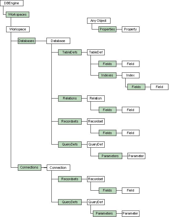
This model has a strict hierarchical structure. There is the object of the upper level in it named DBEngine. All the other objects are included in its collection. Collections arrange instances of one-type objects. For example, any instance of Workspace objects is included in Workspace collection. Each collection belongs to some other object of the hierarchy upper level. Each object, except DBEngine, has a corresponding collection. All collections have the same methods which allow to obtain an object by its name or index in the collection, add, delete and count the objects in this collection. Organization in collection, even though adding numerous objects allows to uniformly add, delete and count objects without remembering names of specific methods for objects of each type. Note. Objects in the collections of this Database access objects model are numerated from zero unlike the objects of the ConceptDraw Access Objects model. To start work with the databases, you should create an instance of DBEngine object. This is the object of the upper level in CDBasic-model access to databases. It operates the driver for database access (odbc32.dll is used for Windows by default) and allows to reach other objects necessary for work with databases. An instance of this object is created by means of the key-word new. Dim eng as DBEngine set eng=new DBEngine Note. DBEngine is one of the few (to be more exact of the three) ConceptDraw objects, an instance of which can be created manually by means of the operator new, and not obtain using other objects. Work with DB runs within workspaces, which manage connections with databases and transactions. A Workspace object corresponds to such a workspace. An instance of this object is stored in Workspaces collection of DBEngine object. At the beginning of the work this collection is empty. That is why a new Workspace instance should be created by calling Create Workspace() method of DBEngine object. This method allows to specify the workspace name as well as login and password for access to the database. Dim eng as DBEngine, ws as Workspace set eng=new DBEngine set ws=eng.CreateWorkspace("name","login","password") Within one workspace it is possible to open several connections and work with them within one transaction - a set of logically connected actions with a database, which transforms the database from one consistent state into another. For work with transactions at workspace level Workspace object has the following methods: BeginTrans() - Opens transaction. All the following actions will be included in this transaction. CommitTrans() - Confirms transaction. Applies all changes in the database, which occurred from the moment of call BeginTrans(). RollbackTrans() - Rolls back transaction. All changes in the database, from the moment of call BeginTrans() will be ignored. For connection with DB either of the two objects can be used: Database or Connection. Database object is a model of open database and it provides access to collections which represent structural elements of the database: tables (collection TableDefs), relations between them (collection Relations), and stored procedures (collection QueryDefs)... Stored procedures and direct SQL queries can be fulfilled using the objects of collection Recordsets of the same Database object. This object also allows to manage transactions. Connection object is a reduced variant of Database object. It allows to make queries to a database, including the stored procedures. It also allows to manage transactions, though not letting manage the database structure directly. In the language of objects it means that Connection object contains collections QueryDefs and Recordsets, but not collections TableDefs and Relations. As at queries to the database Connection object does not have to refresh collections TableDefs and Relations, a query called at Connection object, is being responded quicker. That's why, if you do not work with the database structure, being only interested in the target information contained there, it is recommended to use this object. Basically, it is possible to change and obtain information on the structure with the help of SQL-queries without using Database object at all. But using Database makes stress on the structure also eliminating differences among SQL dialects and makes the code more portable (at least, while it is going about client-server ODBC-drivers). Depending on whether Database or Connection has been chosen for connection to the database, this connection can be found in Databases or Connections collection of the Workspace object. Workspace allows to create and add to its own collections new Database and Connection instances by means of OpenDatabase() and OpenConnection() methods accordingly. Dim eng as DBEngine, ws as Workspace, db as Database set eng=new DBEngine set ws=eng.CreateWorkspace("University","admin","") set db=ws.OpenDatabase("University",TRUE,FALSE,"DSN=University_DSN") or Dim eng as DBEngine, ws as Workspace, cn as Connection set eng=new DBEngine set ws=eng.CreateWorkspace("University","admin","") set cn=ws.OpenDatabase("University",TRUE,FALSE,"DSN=University_DSN") At the end of the work the connection and the workspace should be closed by Close() method of Connection or Database object. After connection has been opened it can be used for making SQL-queries to the database or for work with its structure. To make a query OpenRecordset() method is used. The direct text of the SQL-query / the table name / the name of the stored procedure is given as a parameter. The method returns the Recordset object instance - the object which provides methods of scanning and modification of the resulting data. Dim cn as Connection, rs As Recordset ... set rs=cn.OpenRecordset("SELECT ExpResult FROM ExperimentData") The same method OpenRecordset() allows to specify the cursor type which defines sensitivity of the resulting Recordset to the database changes, that may occur after responding the query. The cursor type is specified by the second parameter. OpenRecordset() method is used for any query to the database. In case, it is going about selection queries, it is the data that is of interest. Recordset object allows for access to them. Recordset object instance contains collection Fields of the given selection. Field is an object, containing name, value, and necessity of an atomic element of the selection. The type and the value are chosen by using one of the properties AsBoolean, AsDouble, AsLong and AsString that return the current field value in according representation. In table representation, field names correspond to the data columns headlines. Selection, as a rule, does not represent just one row (record). But every moment of time one certain row is active and it is this (line) row values that can be extracted from Field object instances. To move between the rows Recordset methods such as MoveNext(), MovePrevious(), MoveFirst(), MoveLast() or Move() are used. The ability of the cursor to move by this or that method depends on cursor type that is passed via OpenRecordset() method, and level of support of the given functionality by the driver and the database. To find out whether the cursor supports the given method, CanMove() method of the same Recordset object can be used. Dim cn as Connection, rs As Recordset, fld as Field Dim sSQL as String ... sSQL = "SELECT ExpResult FROM ExperimentData" set rs=cn.OpenRecordset(sSQL) i=1 Do set fld = rs.Fields.GetByName("ExpResult") trace fld.AsDouble i=i+1 Loop while rs.MoveNext rs.Close() cn.Close() At the end of the work with Recordset its method Close() is called, which closes the cursor and frees the memory allocated for records. Except direct SQL-query strings, in method OpenRecordset() it is possible to pass queries stored in the database as stored procedures. CDBasic supports stored procedures in Transact-SQL format, used in MS SQL Server. CDBasic also allows to obtain and change information about the procedures stored in the database, and also create new ones. For work with the stored procedures QueryDef object exists. Collections of the already existing in the database stored procedures QueryDefs are stored in Database and Connection. To create a new procedure method CreateQueryDef() is called with the name of the procedure and the query string as the parameters. There is also a possibility of creating parameter procedures. For this QueryDef object contains collection Parameters. At the beginning, when creating a new QueryDef instance this collection is empty. To create a new parameter for the stored procedure you need to create a Parameter object instance by calling CreateParameter() method of QueryDef object, customize its properties by specifying its name, type, value and direction (input, input and output, output). The type and the value as well as for Field object are specified by AsBoolean, AsLong, AsDouble, AsString properties. After all the properties have been configured the Parameter instance is joined to a corresponding collection by Append() method. Having finished configuring the QueryDef instance, if necessary, i.e. having joined all the parameters to the collection, the QueryDef itself is joined to the collection of the open database (Connection or Database object). For appending method Append() of QueryDefs collection is used. dim cn as Connection, qd as QueryDef, pr as Parameter ... set qd=cn.CreateQueryDef("new_qd","Select * From Letter WHERE Subject = @sbj") set pr=qd.CreateParameter("sbj", 1, cddbText) qd.Parameters.Append(pr) cn.QueryDefs.Append(qd) Now to call the query saved in the procedure "new_qd" passing its name to OpenRecordset() method is just enough. Now let's move to the database structure. Presentations of the database tables are stored in TableDefs collections. Thus, for instance, it's easy to scan the database to find out what tables it contains. dim eng as DBEngine, ws as Workspace, db as Database, tdf as TableDef set eng=new DBEngine set ws=eng.CreateWorkspace("Workspace 1","login","password") set db=ws.OpenDatabase("Database 1",0,0,"DSN=MyDSN") for i=0 to db.TableDefs.Count-1 set tdf = db.TableDefs.GetByNumber(i) trace tdf.Name next TableDef object represents information about the database fields and table indexes. The first ones are represented in Fields collection (Field object and Fields collection have already been described, when it was going about receiving information from the selection, presented by a Recordset object), the latter in Indexes collection. Besides, TableDef object has the OpenRecordset() method, by means of which you can obtain a selection of all the table contents. It calls with out parameters. To add a new table to the database you need to:
A TableDef instance is created by the Database method. CreateTableDef(), in which the name of the future table is passed. Then, you create the table fields (new instances of Field object). Each of them should be added to the Fields collection table. And then, the already prepared TableDef is added to the TableDefs collection of the Database. It is after it has been added to the collection the new table appears in the active database. Dim db as Database, tbl as TableDef, fld as Field ... set tbl = db.CreateTableDef("TableName") set fld=tbl.CreateField("Name1", cddbByte) tbl.Fields.Append(fld) set fld=tbl.CreateField("Name2", cddbText, 5) tbl.Fields.Append(fld) db.TableDefs.Append(tbl) After the table has physically appeared in the database, indexes can be added to it: the primary key, unique indexes, and the foreign keys. The primary or a unique key can be added directly to Indexes collections of the TableDef. You can do it according to the scheme of adding a table.
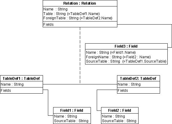
Index fields are selected from the already existing in the table. CreateField() method of Index object considers only the field name. Dim tbl as TableDef, ind as Index, fld as Field ... set ind=tbl.CreateIndex("PR_1") ' the field Student_Id should exist in the table set fld=ind.CreateField("Student_Id") ind.Fields.Append(fld) ind.Primary=True tbl.Indexes.Append(ind) Foreign keys are displayed in Indexes collection of the corresponding TableDef object, but creating them by the CreateIndex() method is impossible. Because it is not about just a peculiarity of a single table, but about links between two different tables, there is a special object for their operation in CDBasic: Relation. This object represents relations between the tables by the following:
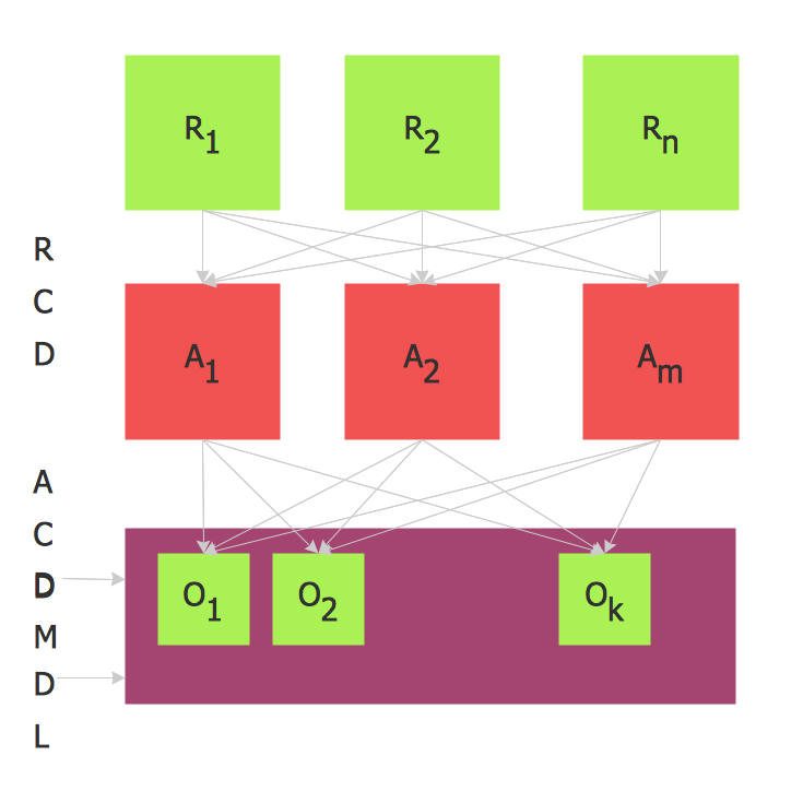
Relation object contains three properties: Name, Table and ForeignTable. Name property identifies an object instance in the collection. Table property contains the table with the primary key name. ForeignTable contains the name of the table with the foreign key, based on this primary key. Besides, there is Fields collection, which contains the fields defining this relation (there is just one such field illustrated here - Field3, but the index can be based on a larger quantity of fields). This field name coincides with the field name in the first table that presents the primary key. ForeignName property - the name of the field, connected to the Name field by a relation coincides with the name of the field from the according table, and SourceTable - with the analogous property of the first table. For adding a relation and the outer index accordingly, you need to:
The given model represents one more type of the database characteristics. It is going about characteristics that can be connected to any object: link, table, stored procedure, relation, index, or field: Any object (but not collection!) has Properties collection. A voluntary number of characteristics (Property object) can be added to it in the most common format: you can give a name, type, and value for such a characteristic. This is the very mechanism, which is used by the database for storing characteristics of its objects. Thus, relation characteristics (Name, Table, ForeignTable) are enumerated in this collection. It can be obtained from CDBasic with the help of Properties collection. Apart from standard characteristics you may need some other ones. Say, for instance, you need to store the relation along with the date of its creation. The following peculiarity is of interest then. Creating a characteristic, you can require it to be inherited by all the objects from its collection. I.e. if you set the appropriate flag when creating a characteristic for the date of creating a relation, then all its fields will get such a characteristic. To create a new characteristic it's enough to call CreateProperty() method of the voluntary object and give him a name by parameters, value and hereditability feature. And then add the appeared object to Properties collection. Dim rl as Relation, pr as Property ... set pr=rl.CreateProperty("CreationDate", Date(), TRUE) rl.Properties.Append(pr) |