SSADM Diagram

The example below illustrates the waterfall model used in SSADM. This model involves 5 stages of developing a product such as requirements specification and its' analysis, design, coding and testing.
Basic CCTV System Diagram. CCTV Network Diagram Example

How to Draw a Computer Network Diagrams

Flow Diagrams

ConceptDraw DIAGRAM diagramming and vector drawing software enhanced with Flowcharts Solution from the "Diagrams" Area of ConceptDraw Solution Park is perfect for easy drawing professional looking Flow Diagrams.
For drawing Flow Diagrams the Flowcharts Solution provides: 2 libraries with commonly used predesigned vector objects - Flowchart library and Flowcharts Rapid Draw library; collection of Flow Diagrams samples; Basic Flowchart template.
Best Program to Make Workflow Diagrams

How To Draw a Diagram

You mau choose to start from one of plenty diagram templates or to use your own idea.
Use the Best FlowChart Tool for the Job

Flowchart Components

This circular arrows diagram sample shows the systems development life cycle (SDLC) stages.
"The systems development life cycle (SDLC), also referred to as the application development life-cycle, is a term used in systems engineering, information systems and software engineering to describe a process for planning, creating, testing, and deploying an information system. The systems development life-cycle concept applies to a range of hardware and software configurations, as a system can be composed of hardware only, software only, or a combination of both." [Systems development life-cycle. Wikipedia]
The arrow circle diagram example "Systems development life cycle" was created using the ConceptDraw PRO diagramming and vector drawing software extended with the Circular Arrows Diagrams solution from the area "What is a Diagram" of ConceptDraw Solution Park.
Circular arrows diagram

How to Draw an Organization Chart

While making the drawing process easier and faster.
Video tutorial on creating orgchart with ConceptDraw products. Try ConceptDraw for creating orgchart professional presentations!
How to Draw Business Process Diagrams with RapidDraw Interface

Process Flowchart


Making Mechanical Diagram

Workflow Diagram Software Mac

Use the ConceptDraw DIAGRAM professional Mac OS X software for drawing workflow diagram. The Workflow Diagrams solution with its libraries and templates set make the possibility to identify resources that are required for work goal implementation. The process flow diagram identify flow which occurs as network of process dependencies, organizational decisions and interactions between departments. Usually workflow diagrams show business participants actions that carry product or service to the final destination, the consumer.
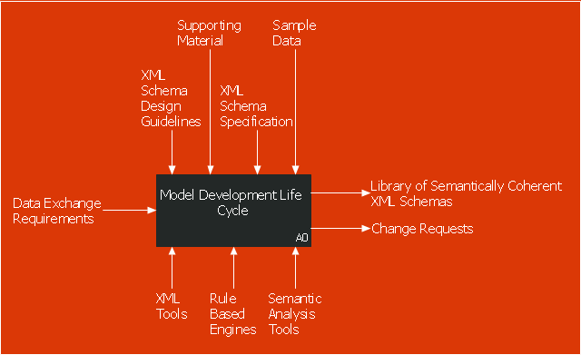
This IDEF0 diagram sample was created on the base of the figure from the website of the Engineering Laboratory of the National Institute of Standards and Technology (NIST). [mel.nist.gov/ msidlibrary/ doc/ kc_ morris/ gsa-final_ files/ image002.gif]
"The systems development life cycle (SDLC), also referred to as the application development life-cycle, is a term used in systems engineering, information systems and software engineering to describe a process for planning, creating, testing, and deploying an information system. The systems development life-cycle concept applies to a range of hardware and software configurations, as a system can be composed of hardware only, software only, or a combination of both." [Systems development life cycle. Wikipedia]
The IDEF0 diagram example "Model development life cycle" was created using the ConceptDraw PRO diagramming and vector drawing software extended with the IDEF0 Diagrams solution from the Software Development area of ConceptDraw Solution Park.
IDEF0 diagram
Building Drawing. Design Element — Plumbing

Technical Drawing Software

Why Flowchart Important to Accounting Information System?

Flowcharts are used to represent accounting information in a system. There are special symbols which are used to create accounting flowcharts. Try conceptdraw flowcharting set of symbols to draw a professional charts.
Process Flowchart Symbols

HelpDesk
How to Create an IDEF0 Diagram for an Application Development

- Process Flowchart | JSD - Jackson system development | Systems ...
- Systems development life cycle | Explain System Development ...
- Systems development life cycle | SSADM Diagram | Process ...
- Systems development life cycle | Draw Diagram Of Information ...
- Drawing System Development Cycle
- Systems development life cycle | Block Diagrams | Circular Arrows ...
- Draw The System Development Cycle
- Process Flowchart | Systems development life cycle | JSD - Jackson ...
- Draw A Sgmple Sketch Of System Development Cycle
- Systems development life cycle | Process Flowchart | JSD - Jackson ...
- Draw The Structure Of Development Cycle
- Model development life cycle - IDEF0 diagram | Circular Arrows ...
- What Is The Use Of System Fow Charts In System Development Cycle
- Drow System Development Cycle
- Systems development life cycle | SSADM Diagram | Circular Flow ...
- Process Flowchart | Basic Flowchart Symbols and Meaning ...
- Information System Resource With Sketch
- | Symbol Of A Sketched Project Life Cycle Diagram
- Cycle Diagram Software
- Draw The System Development Cycle Diagram
- ERD | Entity Relationship Diagrams, ERD Software for Mac and Win
- Flowchart | Basic Flowchart Symbols and Meaning
- Flowchart | Flowchart Design - Symbols, Shapes, Stencils and Icons
- Flowchart | Flow Chart Symbols
- Electrical | Electrical Drawing - Wiring and Circuits Schematics
- Flowchart | Common Flowchart Symbols
- Flowchart | Common Flowchart Symbols