Booch OOD Diagram

Object-Oriented Development (OOD) Method

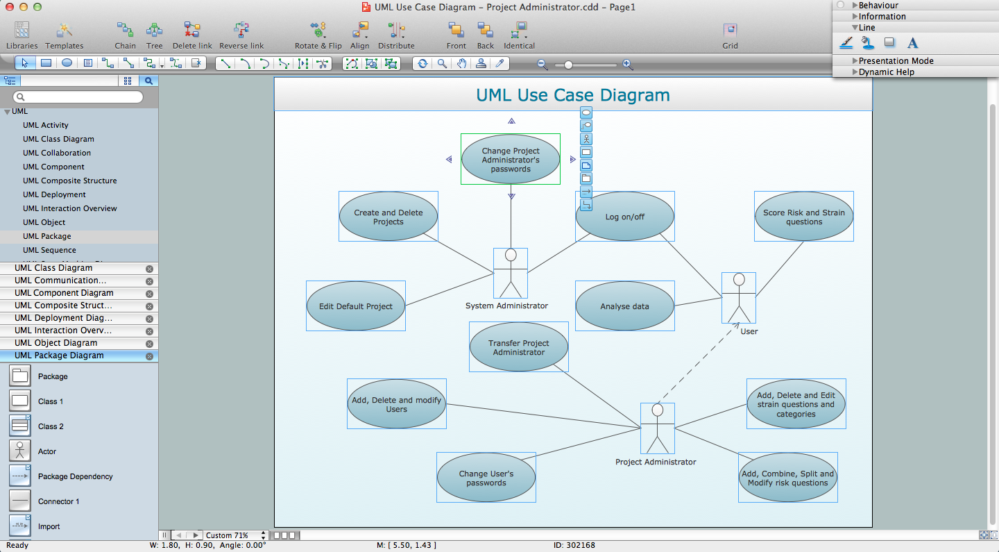
This sample was created in ConceptDraw DIAGRAM diagramming and vector drawing software using the Rapid UML Solution from the Software Development area of ConceptDraw Solution Park.
UML for Software Engineers
Software Diagrams

ConceptDraw DIAGRAM is a perfect tool for Designing and planning tasks; Developing Visualization Solutions; Project Planning (Gantt Charts, Timelines, Project Schedules).
UML Composite Structure Diagram. Design Elements

ConceptDraw has 393 vector stencils in the 13 libraries that helps you to start using software for designing your own UML Diagrams. You can use the appropriate stencils of UML notation from UML Composite Structure library.
Examples for OOSE Method

UML Business Process

Yourdon and Coad Diagram

SSADM Diagram

The example below illustrates the waterfall model used in SSADM. This model involves 5 stages of developing a product such as requirements specification and its' analysis, design, coding and testing.
ER Diagram Tool

Software and Database Design with ConceptDraw DIAGRAM

UML diagramming; designing and prototyping Graphical User Interface (GUI); flowcharts, data flow diagrams; database and ERD diagramming (Chen ERD, Database Model diagram, Express-G, Martin ERD, ORM Diagrams and more); SSADM diagrams, Booch diagrams, Nassi-Shneiderman diagrams with special flowchart symbols.
About UML

This sample shows the work of the taxi service and is used by taxi stations, by airports, in the tourism field and delivery service.
Software Diagram Examples and Templates

Software Development area of ConceptDraw Solution Park provides 5 solutions:
Data Flow Diagrams, Entity-Relationship Diagram (ERD), Graphic User Interface, IDEFO Diagrams, Rapid UML.
Jacobson Use Cases Diagram

- Diagrams Used In Booch Methodology
- Booch OOD Diagram | Software Diagrams | Yourdon and Coad ...
- Booch OOD Diagram | Object-Oriented Development (OOD) Method ...
- Booch OOD Diagram | Examples for OOSE Method | Object-Oriented ...
- Booch OOD Diagram | Object-Oriented Development (OOD) Method ...
- Diagrams Used In Booch Methodology In Ooad
- Yourdon and Coad Diagram | Booch OOD Diagram | Design Data ...
- Object-Oriented Development (OOD) Method | Booch OOD Diagram ...
- Booch OOD Diagram | Jacobson Use Cases Diagram | Er Diagram ...
- Database Design | Booch OOD Diagram | UML Flowchart Symbols ...
- DFD Flowchart Symbols | Booch OOD Diagram | Jacobson Use ...
- Booch OOD Diagram | Program Structure Diagram | OMT Method ...
- Booch OOD Diagram | Software Diagrams | About UML | Object ...
- Booch OOD Diagram | OOSE Method | About UML | Object Oriented ...
- Booch OOD Diagram | What is Gantt Chart (historical reference ...
- Booch OOD Diagram | OMT Method | Object-Oriented Development ...
- Booch OOD Diagram | Software Diagrams | Yourdon and Coad ...
- Booch OOD Diagram | Software Diagram Examples and Templates ...
- Booch OOD Diagram | Examples for OOSE Method | OOSE Method ...
- OOSE Method | Booch OOD Diagram | OMT Method | Uml Method
- ERD | Entity Relationship Diagrams, ERD Software for Mac and Win
- Flowchart | Basic Flowchart Symbols and Meaning
- Flowchart | Flowchart Design - Symbols, Shapes, Stencils and Icons
- Flowchart | Flow Chart Symbols
- Electrical | Electrical Drawing - Wiring and Circuits Schematics
- Flowchart | Common Flowchart Symbols
- Flowchart | Common Flowchart Symbols