UML Use Case Diagram Example - Taxi Service

UML Class Diagram Notation

Taxi Service Data Flow Diagram DFD Example

UML Use Case Diagram Example - Estate Agency

Diagramming Software for Design UML Collaboration Diagrams


Sequence Diagram Tool

UML Tool & UML Diagram Examples

Business Process Modeling Notation Template

 Rapid UML
Rapid UML solution extends ConceptDraw DIAGRAM software with templates, samples and libraries of vector stencils for quick drawing the UML diagrams using Rapid Draw technology.
Create Professional Looking Diagrams
.png "Create Professional Looking Diagrams *")
Introductory Guide to Rapid UML Solution

Class Diagram Tool

UML Tool & UML Diagram Examples
Software Diagram Examples and Templates

Business Process Modeling with ConceptDraw

Activity Network (PERT) Chart
 Chart *")
Workflow Diagram Data

"Banks offer many different channels to access their banking and other services:
(1) Automated Teller Machines.
(2) A branch is a retail location.
(3) Call center.
(4) Mail: most banks accept cheque deposits via mail and use mail to communicate to their customers, e.g. by sending out statements.
(5) Mobile banking is a method of using one's mobile phone to conduct banking transactions.
(6) Online banking is a term used for performing multiple transactions, payments etc. over the Internet.
(7) Relationship Managers, mostly for private banking or business banking, often visiting customers at their homes or businesses.
(8) Telephone banking is a service which allows its customers to conduct transactions over the telephone with automated attendant or when requested with telephone operator.
(9) Video banking is a term used for performing banking transactions or professional banking consultations via a remote video and audio connection. Video banking can be performed via purpose built banking transaction machines (similar to an Automated teller machine), or via a video conference enabled bank branch clarification.
(10) DSA is a Direct Selling Agent, who works for the bank based on a contract. Its main job is to increase the customer base for the bank." [Bank. Wikipedia]
The UML use case diagram example "Banking system" was created using the ConceptDraw PRO diagramming and vector drawing software extended with the Rapid UML solution from the Software Development area of ConceptDraw Solution Park.
UML use case diagram

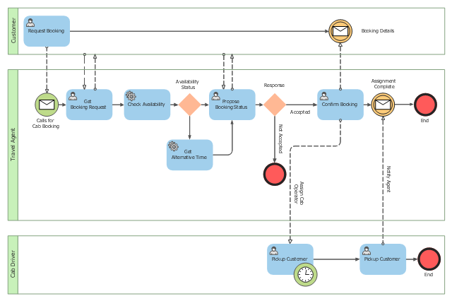
This BPMN (Business Process Model and Notation) collaboration diagram sample depicts interactions between customer, travel agent and cab driver, which are defined as a sequence of activities, and represent the message exchange during a cab booking process.
"Business process modeling is used to communicate a wide variety of information to a wide variety of audiences. BPMN is designed to cover this wide range of usage and allows modeling of end-to-end business processes to allow the viewer of the Diagram to be able to easily differentiate between sections of a BPMN Diagram. There are three basic types of sub-models within an end-to-end BPMN model: Private (internal) business processes, Abstract (public) processes, and Collaboration (global) processes...
Collaboration (global) processes.
A collaboration process depicts the interactions between two or more business entities. These interactions are defined as a sequence of activities that represent the message exchange patterns between the entities involved. Collaboration processes may be contained within a Pool and the different participant business interactions are shown as Lanes within the Pool. In this situation, each Lane would represent two participants and a direction of travel between them. They may also be shown as two or more Abstract Processes interacting through Message Flow. These processes can be modeled separately or within a larger BPMN Diagram to show the Associations between the collaboration process activities and other entities. If the collaboration process is in the same Diagram as one of its corresponding private business process, then the activities that are common to both processes can be associated." [Business Process Model and Notation. Wikipedia]
The business process modeling diagram example "Cab booking public process - Collaboration BPMN 2.0 diagram" was designed using the ConceptDraw PRO diagramming and vector drawing software extended with the Business Process Diagram solution from the Business Processes area of ConceptDraw Solution Park.
Business process modeling
Product Overview

- Class Diagram Of Cab Management System
- Use Case Diagram For Cab Management System
- Rapid UML | Cab Management System Class Diagram Explain
- Deployment Diagram For Cab Management System
- Rapid UML | Rapid UML | Object Diagram For Cab Management ...
- IDEF3 Standard | Rapid UML | State Machine Diagram Taxi ...
- Diagrams For Cab Management System
- Class Diagram For Cab Booking System
- Sequence Diagram For Cab Booking System
- State Chart Diagram Of Cab Management System
- Component And Deployment Diagram For Taxi Service Management
- Use Case Diagram For Online Cab Booking System
- Online Cab Management System Er Diagram
- Actitvity Diagram For Taxi Management System
- Online Cab Booking System Class Diagram
- Uml Simple Object Model Cab Management
- Activity Diagram On Cab Booking System
- UML Use Case Diagram Example - Taxi Service | Business Process ...
- Use Case Diagram Airport Management System