HelpDesk
How To Create Risk Diagram (PDPC) Using Solutions

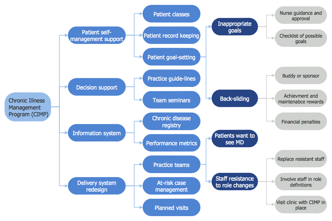
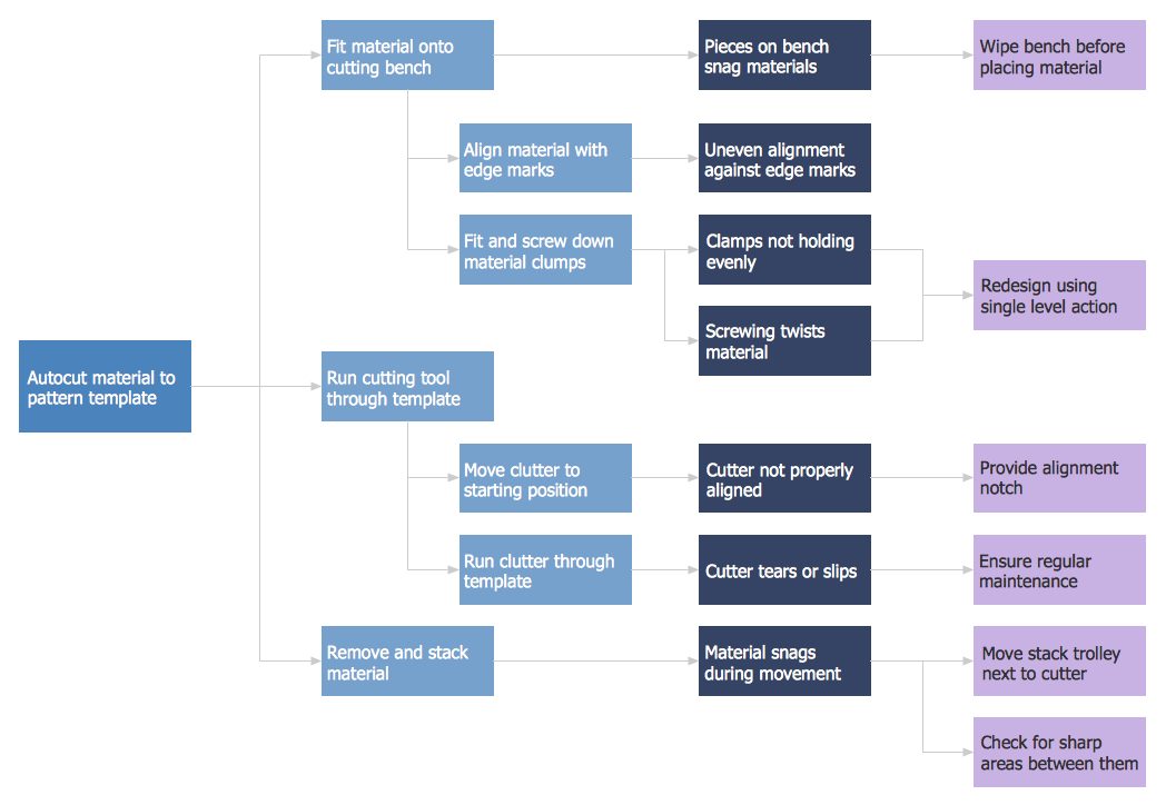
Risk Diagram (Process Decision Program Chart)
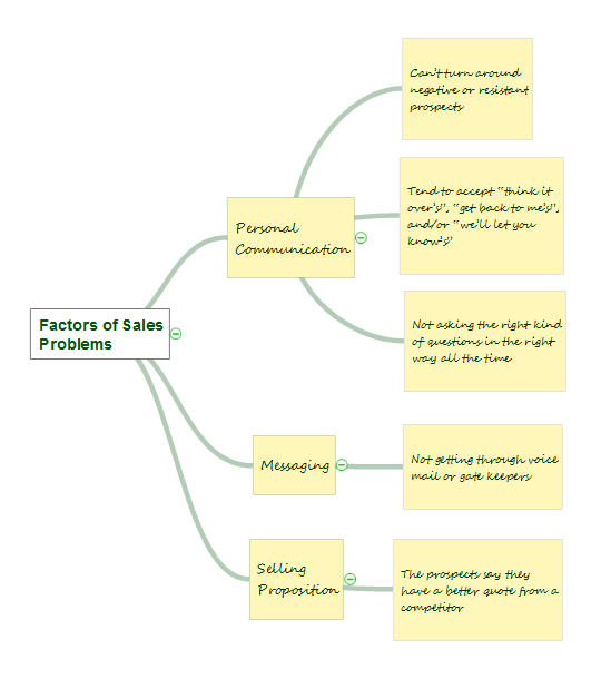
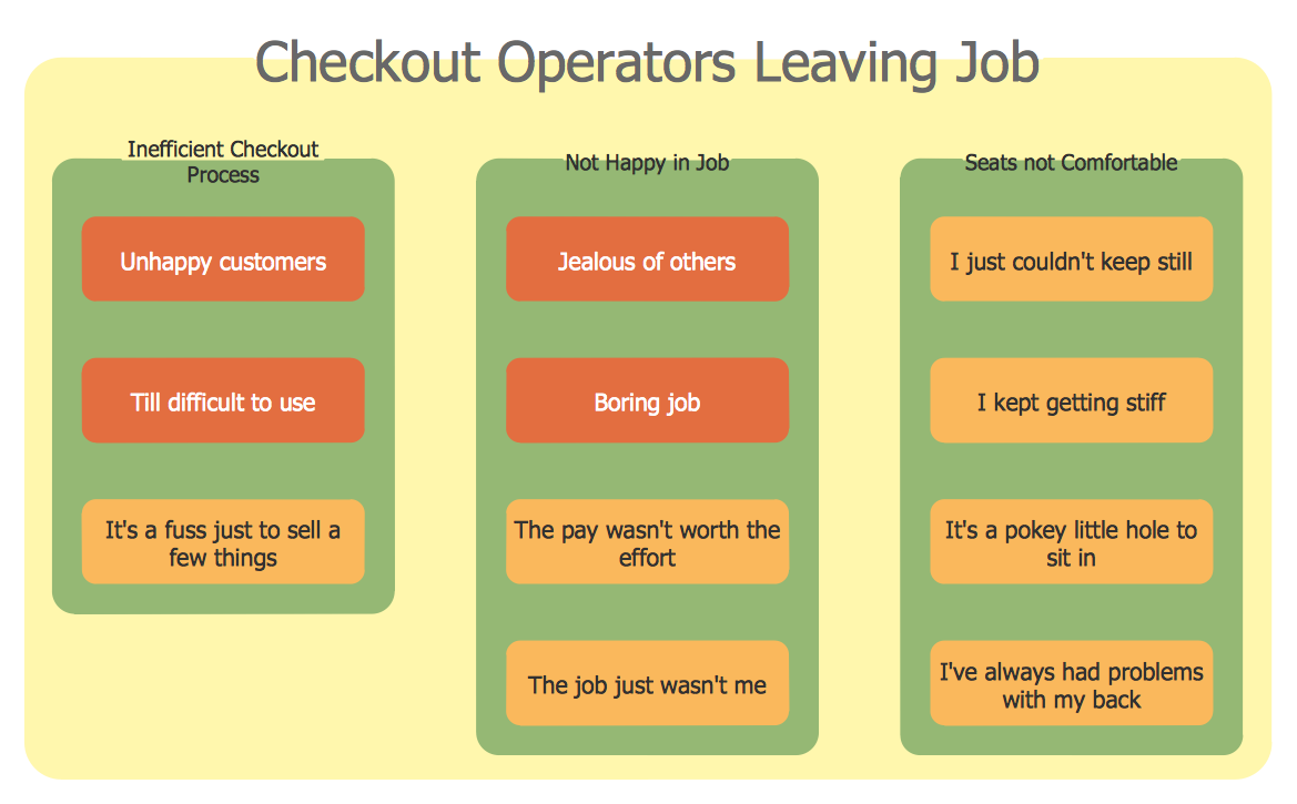
Affinity Diagram
Risk Diagram (Process Decision Program Chart)
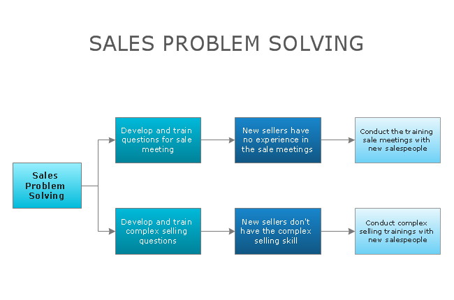
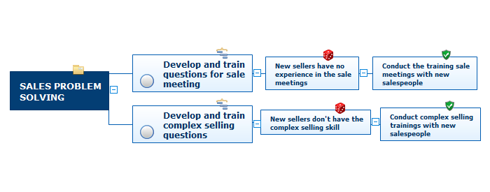
CORRECTIVE ACTIONS PLANNING. Risk Diagram (PDPC)

Root Cause Tree Diagram

Activity Network Diagram Method

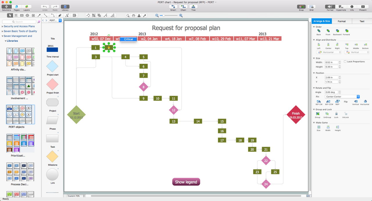
Activity Network (PERT) Chart

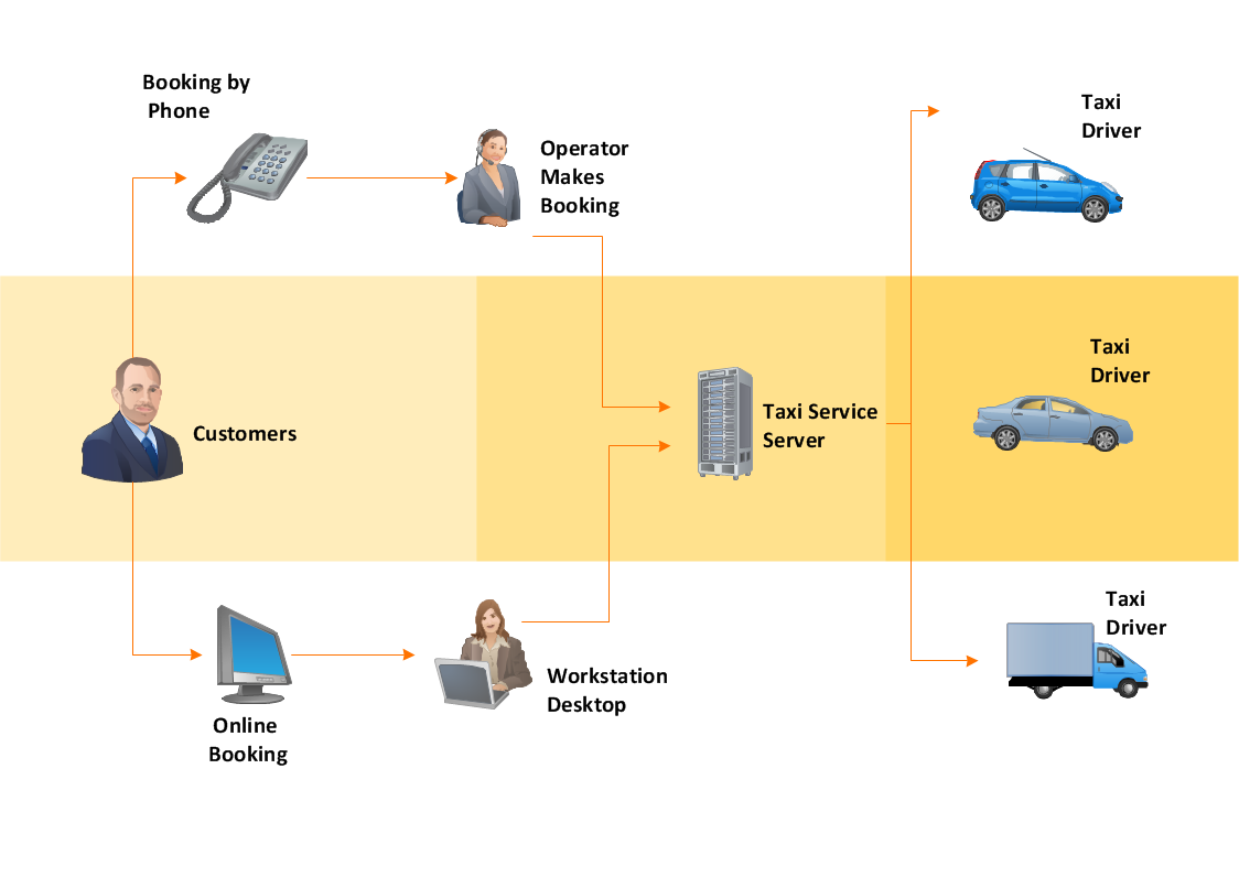
Workflow Diagram
UML Sample Project

PDPC
Affinity Diagram
PERT Chart Software
Pyramid Diagram
Developing Entity Relationship Diagrams

- CORRECTIVE ACTIONS PLANNING. Risk Diagram (PDPC) | How ...
- CORRECTIVE ACTIONS PLANNING. Risk Diagram (PDPC) | Risk ...
- How To Create Risk Diagram (PDPC) | How to Manage Problem ...
- Corrective Action Planning | Preventive Action | How To Create Risk ...
- How To Create Risk Diagram (PDPC) | The Action Plan | How to Use ...
- How To Create Risk Diagram (PDPC)
- PROBLEM ANALYSIS. Prioritization Matrix | How To Create Risk ...
- 5 Level pyramid model diagram - Information systems types | How ...
- Circle-Spoke Diagrams | How To Create Risk Diagram (PDPC ...
- CORRECTIVE ACTIONS PLANNING. Risk Diagram (PDPC) | How ...
- CORRECTIVE ACTIONS PLANNING. Risk Diagram (PDPC) | How ...
- How To Create Risk Diagram (PDPC) | How to Manage Problem ...
- How To Create Risk Diagram (PDPC) | Management Area | How to ...
- Sample Risk Management Plan Template Chart
- PDPC | Risk diagram (PDPC) - Template | Process decision ...
- CORRECTIVE ACTIONS PLANNING. Risk Diagram (PDPC) | How ...
- CORRECTIVE ACTIONS PLANNING. Risk Diagram (PDPC) | How ...
- Positioning Map | SWOT analysis positioning matrix - Template ...
- The Action Plan | PROBLEM ANALYSIS. Prioritization Matrix | How ...