Made with
ConceptDraw
DIAGRAM 18

Workflow Diagram

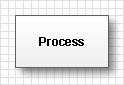
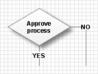
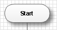
A workflow represents the transferring of data, documents or tasks during a work process. To make it easier to study and analyze working processes, and to present them in a simple visual manner, workflow diagrams are used. Diagrams allow you to follow the path of a task in a workflow, identify the person who responsible for its execution at each stage, show which documents the task is accompanied by and the resources it needs. By knowing this, it is possible to optimize the workflow and to discover its weak points. A workflow diagram is a type of flowchart. These diagrams consist of three types of blocks:

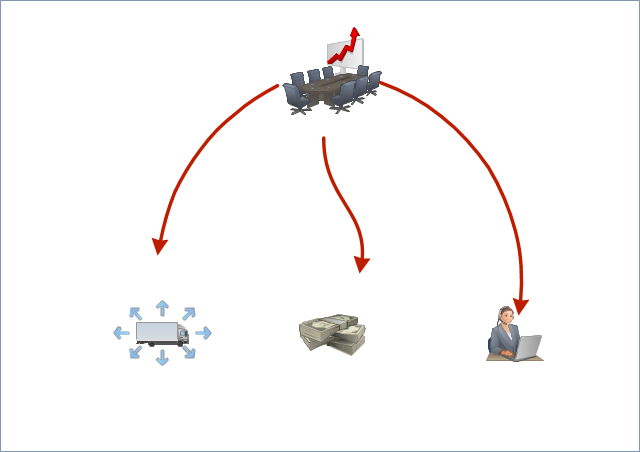
Graphic representation Diagram element
Study, analysis or process
Decision making
Workflow start and finish

During study and analysis, the accuracy of decisions made earlier and the availability of all necessary information and resources are checked. For example before beginning production, the fulfilment of product repayment terms, product quality and completeness are evaluated. When analysis stage is complete, decision making is required. The making decision block has two outputs - YES and NO. If the task can’t be solved unambiguously, several conditions are studied and analyzed, leading to several decision variants, meaning several consecutive decision making blocks are applied. Answers to all questions of each block lead to necessary actions.

After making a decision, the process representing the totality of events starts. If a negative decision is made, the workflow may be stopped or even a return to a previous point in the workflow can occur.

When building a work flow diagram it is necessary to create a list of all processes constituting the working process so that connecting them to each other with blocks of study and analysis, and block of decisions, creates a complete picture of the workflow.

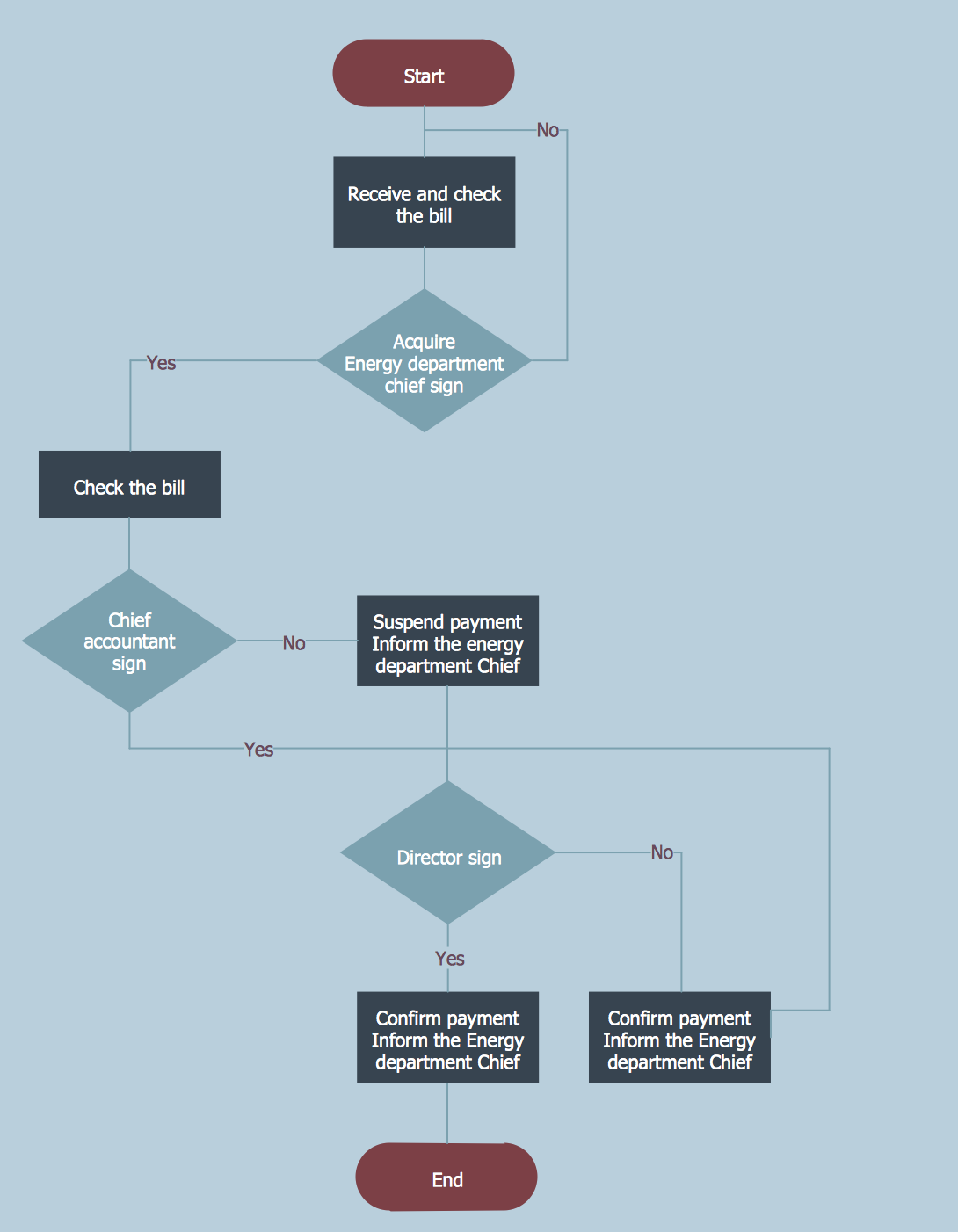
Below is an example of a workflow diagram showing the payment process of an account for electricity consumed by an enterprise.

Workflow Diagram

Example 1. Workflow Diagram

The received account is checked by an enterprise power engineering specialist to control its correspondence with regards to the electricity consumption report. Then a decision on signing the account by the specialist is made. If the account data corresponds with the report data the account is signed, otherwise it is necessary to correct the account details. After this, the account is signed by the enterprise accountant general, who makes a decision on signing the account relying on the presence of the power engineering specialist signature and the analysis of the enterprise financial statements. After the account is signed by the accountant general, it is signed by the enterprise chief who makes a decision on the account signing and payment relying on the presence of signatures of the accountant general and power engineering specialist and current financial priorities of the enterprise.

As shown, a workflow diagram built correctly and competently can represent any workflow in your company quickly, clearly and visually.

Workflow Diagram *

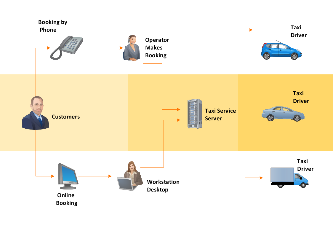
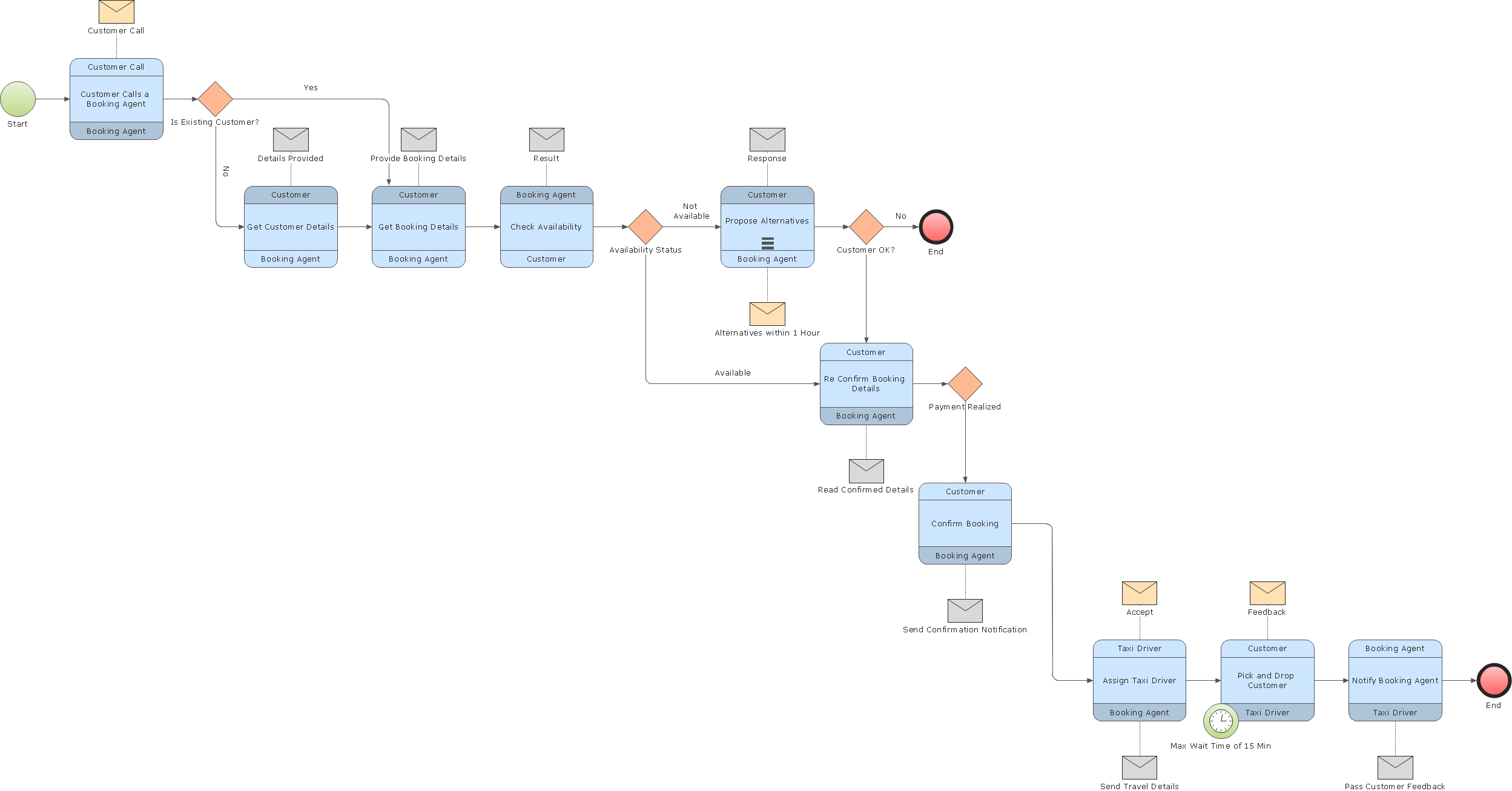
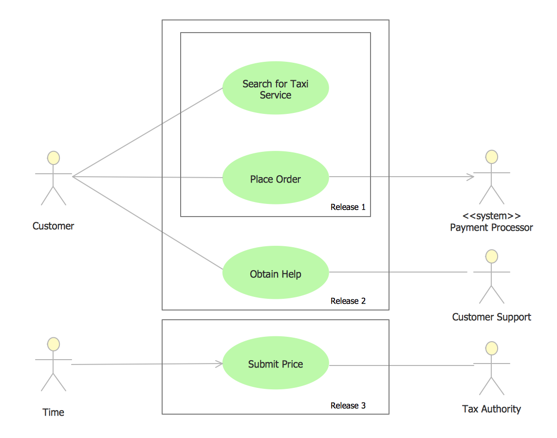
Example 2. Workflow Diagram - Taxi Service

The following features make ConceptDraw DIAGRAM extended with the Workflow Diagrams Solution the most effective diagramming software:

  1. You don't need to be an artist to draw professional looking diagrams in a few minutes.
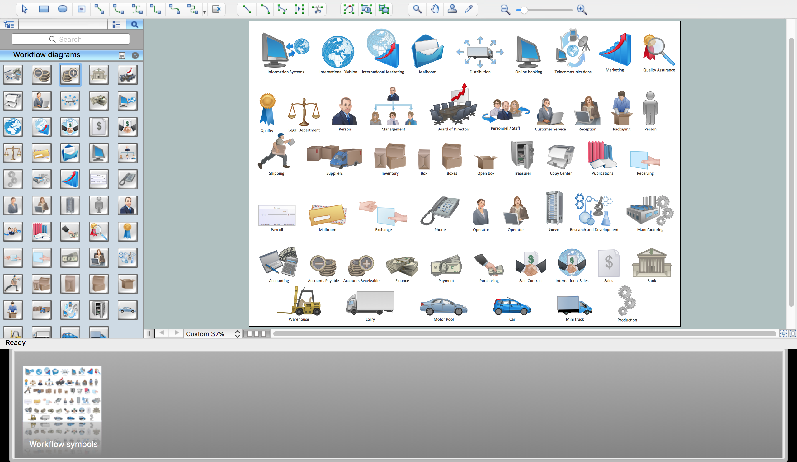
  2. Large quantity of ready-to-use vector objects makes drawing your diagrams quick and easy.
  3. Extensive collection of pre-designed templates and samples give you a great start for your own diagrams.
  4. ConceptDraw DIAGRAM provides you with the possibility to use the grid, rules and guides. You can easily rotate, group, align, and arrange objects, and use different fonts and colors to make your diagram stand out.
  5. All ConceptDraw DIAGRAM documents are vector graphic files and are available for reviewing, modifying, and converting to a variety of formats: image, HTML, PDF file, MS PowerPoint Presentation, Adobe Flash, MS Visio.
  6. Using ConceptDraw STORE you can navigate through ConceptDraw Solution Park, managing downloads and updates. You can access libraries, templates and samples directly from ConceptDraw STORE.
  7. If you have any questions, our support is free of charge and always ready to come to your aid.


TEN RELATED HOW TO's:
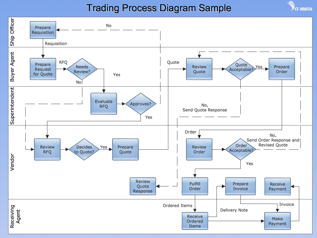
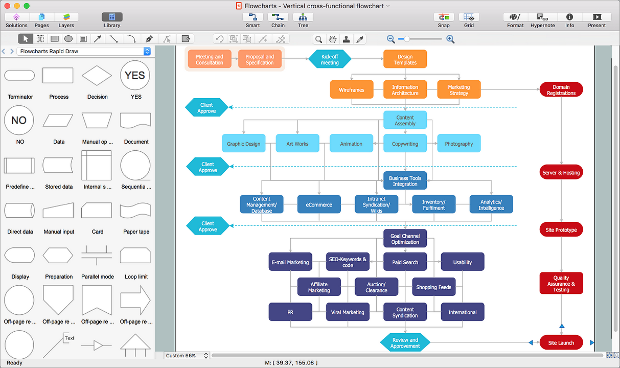
Working with information can be quite tedious, furthermore, some data can be quite difficult to perceive without any graphic representation. So, to facilitate your work, you can use business diagrams, such as simple flowcharts or Gantt charts for project management and orgcharts for clarifying your company structure. You can use a proper software, like ConceptDraw Pro, draw them on paper, or use whiteboards, but it is more convenient to use a digital tool. This diagram shows a cross-functional flowchart that was made fore telecom service provider. A workflow of a common telecommunication service provider has a rather branched structure. Thus, it is useful to have a flow chart to visualize the sequences and interrelations of the work flow steps. Business process flowchart contains 17 processes and 4 decision points,that are distributed through 2 lines depicting the participants involved. Also there are connectors that show the data flow within processes. This flowchart displays a detailed model of the telecom service trading process, as well as all participants in the process and how they interact with each other.Business diagrams & Org Charts with ConceptDraw DIAGRAM  *
Picture: Business diagrams & Org Charts with ConceptDraw DIAGRAM
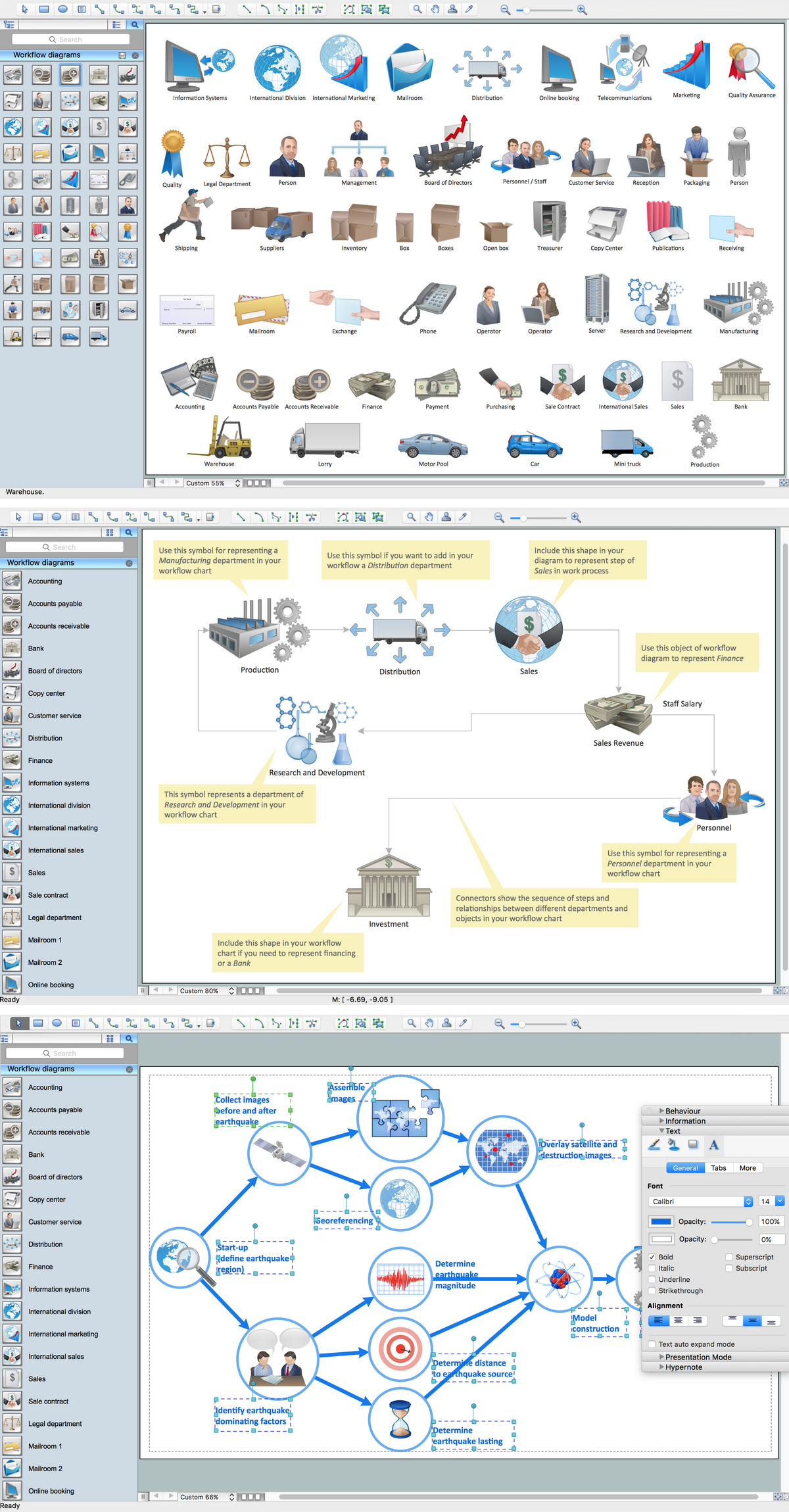
ConceptDraw DIAGRAM application is perfect for creating workflow diagrams. This application contains specific features and technologies designed to draw diagrams faster, such as RapidDraw and Arrows10. ConceptDraw DIAGRAM software extended with the Workflow Diagrams solution gives you a flexible tool to draw any kind of workflow.Workflow Application *
Picture: Workflow Application
Related Solution:
This sample was created in ConceptDraw DIAGRAM diagramming and vector drawing software using the Organizational Charts Solution from the Software Development area of ConceptDraw Solution Park. This sample shows the organizational chart in the field of Architect Engineering. Create your own orgchart professional drawings using ConceptDraw.Business Board Org Chart *
Picture: Business Board Org Chart
Related Solution:
ConceptDraw DIAGRAM extended with Workflow Diagrams solution from the Business Processes area is a powerful workflow diagram software which offers you a variety of workflow examples.Workflow Examples *
Picture: Workflow Examples
Related Solution:
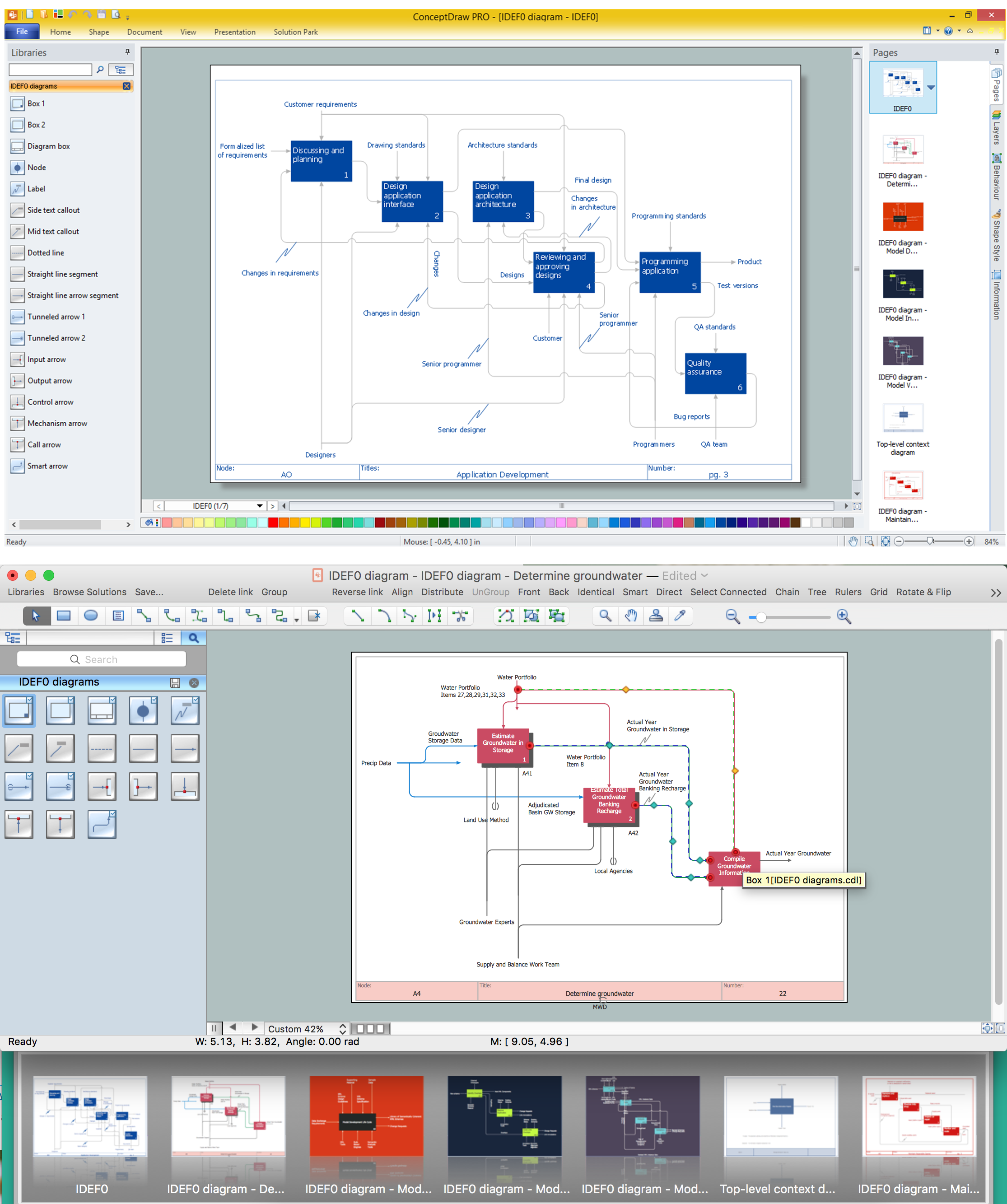
The most worked out and commonly used methodology of business processes description is IDEF methodology. Besides business processes it allows to describe functional blocks, for example production and marketing. ConceptDraw lets creation of business processes description using IDEF0 and IDEF2 methods.Business Processes *
Picture: Business Processes
Related Solution:
Block diagrams solution extends ConceptDraw DIAGRAM software with templates, samples and libraries of vector stencils for creating the block diagram. Create block diagrams, electrical circuit diagrams, schematics, and more in minutes with ConceptDraw DIAGRAM.Create Block Diagram *
Picture: Create Block Diagram
The behavior of worker in organization is influences organizational effectiveness. A simple block diagram made with ConceptDraw Block diagrams solution can improve the understanding of expectations of workers regarding what they l contribute to organization and what they wait to obtain. Making block diagram depicting the individual behavior in organization is used in HR management to obtain an optimal and positive overall contribution to the organization. The behavior of worker in organization is influences organizational effectiveness. A simple block diagram made with ConceptDraw Block diagrams solution can improve the understanding of expectations of workers regarding what they l contribute to organization and what they wait to obtain. Making block diagram depicting the individual behavior in organization is used in HR management to obtain an optimal and positive overall contribution to the organization.Basic Diagramming *
Picture: Basic Diagramming
Related Solution:
When describing any computer network, we imagine a set of devices and nodes, arranged in some way. Talking about network structures, we should distinguish physical and logical network topologies, as physical topology is about devices location and logical topology illustrates data flow. In the same time, they do not have to match, and some devices, such as repeaters, may have a physical star layout, but a bus logical topology. There are two main types of computer network topologies: Physical topology that show the physical organization of a network - equipment and types of connections. Star network topology involves a set of devices that is connected to a single hub (router). Ring network topology means that, devices connected according this topology have two connections, connecting with nearby devices to make a loop. Bus network topology is the topology presented at the current diagram. It is similar to a ring topology. The difference is that data moves up and down a linear connection, copying itself where network equipment works as bus-stations along the way. This network topology can be used for small network, or when adding an extra device into a network.Network Topologies
Picture: Network Topologies
Related Solution:
Affinity Diagram Software - ConceptDraw DIAGRAM is a powerful diagramming and vector drawing software that allows quick, easy and effective create the Affinity Diagrams. Seven Management and Planning Tools solution from the Business Productivity area of ConceptDraw Solution Park provides templates, samples and ready-to-use vector stencils that will help you design the professional looking Affinity Diagrams in a few moments.Affinity Diagram Software *
Picture: Affinity Diagram Software
Related Solution:
ConceptDraw Flowcharts visualize a process or algorithm of program as step/operation blocks of various shapes connected with arrowed lines showed the process flow direction. They are used to visualize business or technical processes and software algorithms.Selecting & Creating Flowcharts *
Picture: Selecting & Creating Flowcharts
Related Solution:
ConceptDraw
DIAGRAM 18