UML Class Diagram Generalization Example UML Diagrams

This sample describes the use of the classes, the generalization associations between them, the multiplicity of associations and constraints. Provided UML diagram is one of the examples set that are part of Rapid UML solution.
UML Class Diagram Notation

This vector stencils library contains 54 BDD symbols.
Use it to design your block definition diagrams using ConceptDraw PRO diagramming and vector drawing software.
"Block Definition Diagram
A block definition diagram is based on the UML class diagram, with restrictions and extensions as defined by SysML. ...
Block and ValueType Definitions
A SysML Block defines a collection of features to describe a system or other element of interest. A SysML ValueType
defines values that may be used within a model. SysML blocks are based on UML classes, as extended by UML composite structures. SysML value types are based on UML data types. Diagram extensions for SysML blocks and value types are described by other subheadings of this sub clause." [www.omg.org/ spec/ SysML/ 1.3/ PDF]
The vector stencils library "Block definition diagram" is included in the SysML solution from the Software Development area of ConceptDraw Solution Park.
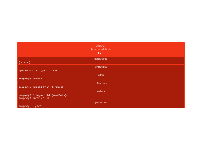
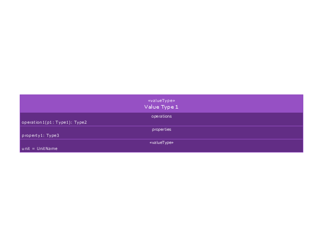
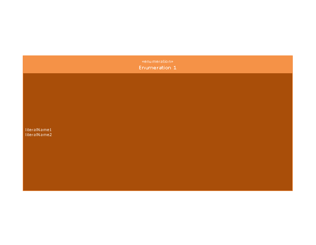
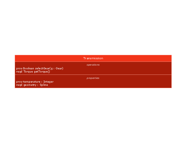
Block definition diagram
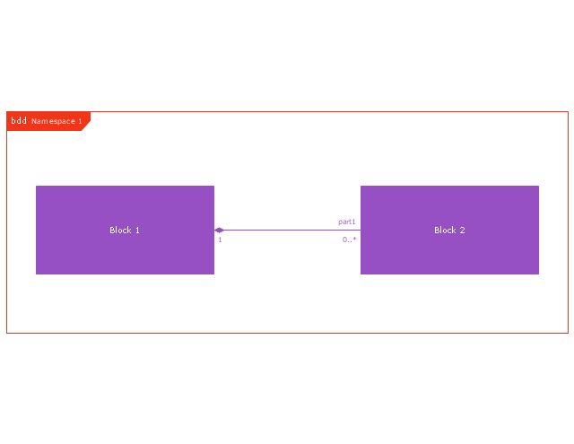
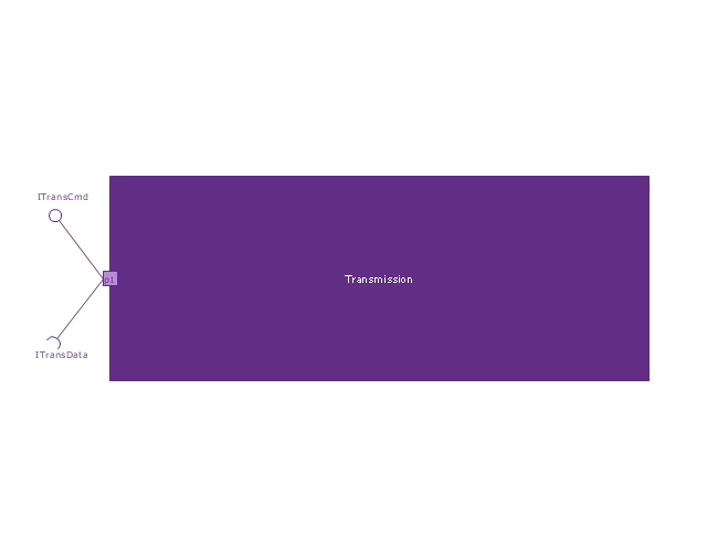
Block
Actor

Actor 2

Value type
Enumeration
Abstract definition

Abstract definition 2
Abstract definition 3
Stereotype property compartment

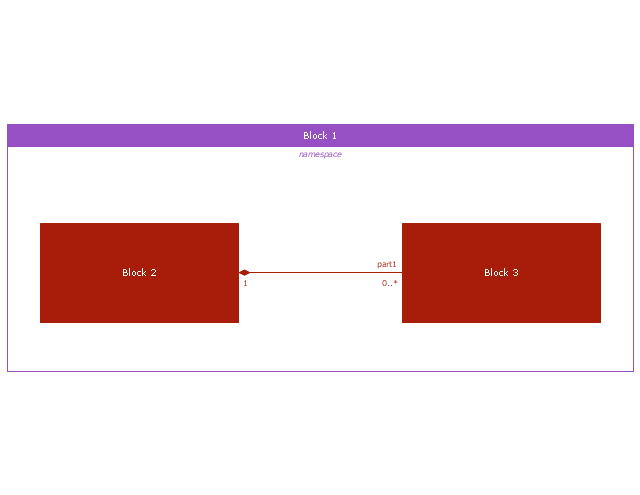
Namespace compartment
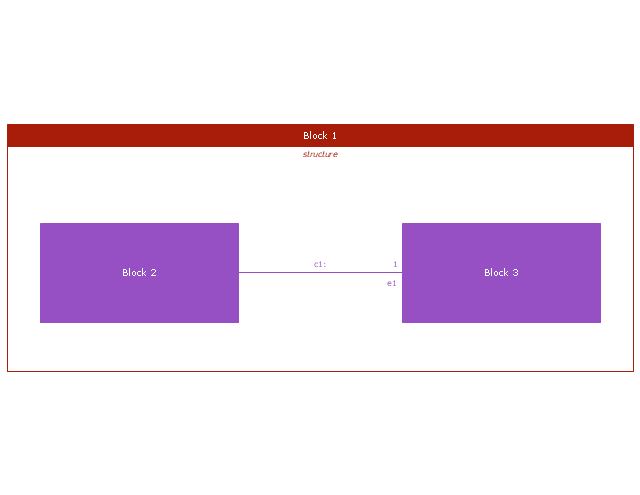
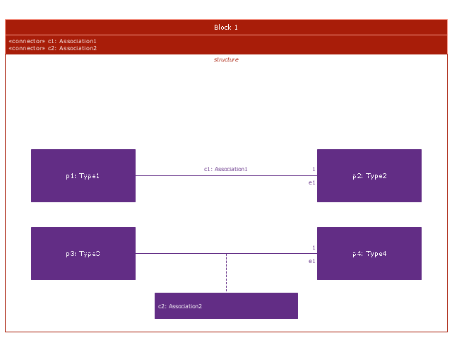
Structure compartment
Unit

Unit 2

Quantity kind

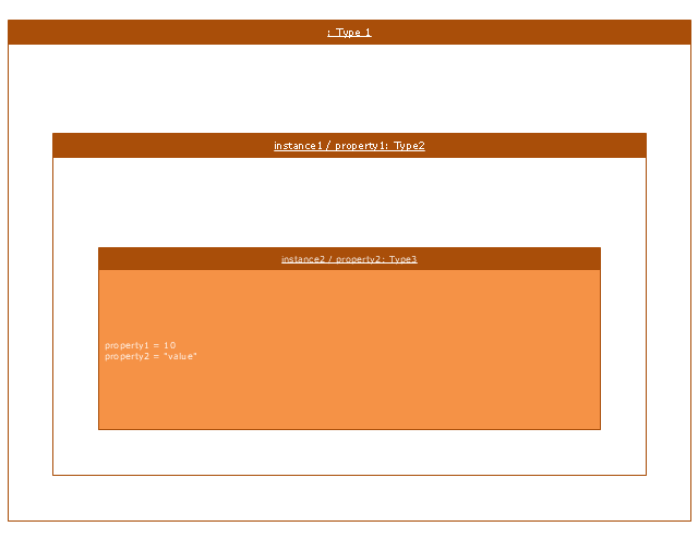
Instance specification
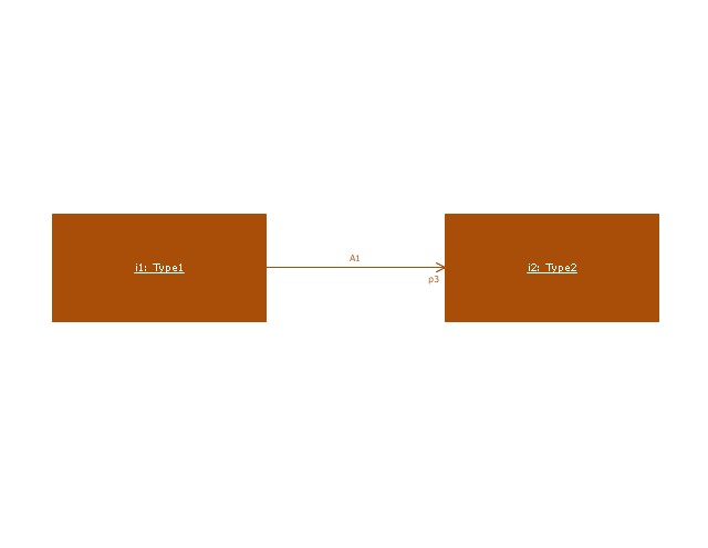
Instance specification 2

Instance specification 3

Instance specification 4
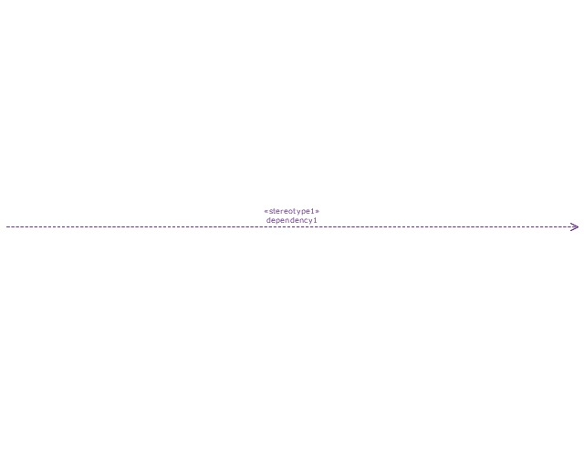
Dependency
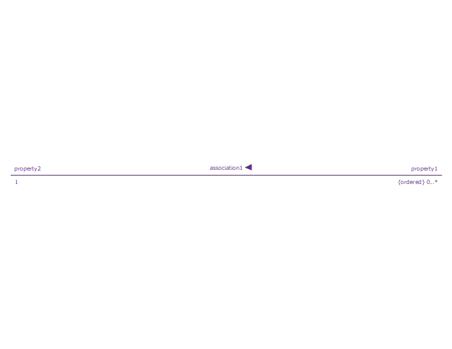
Reference association
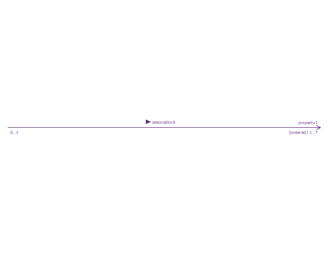
Reference association 2
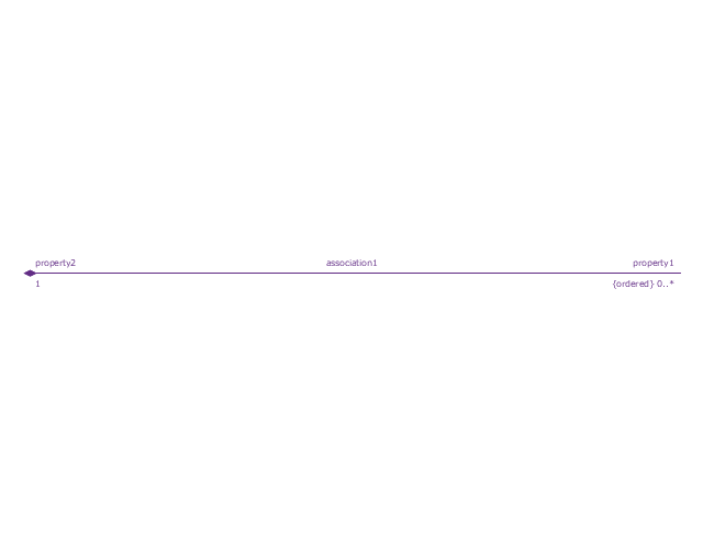
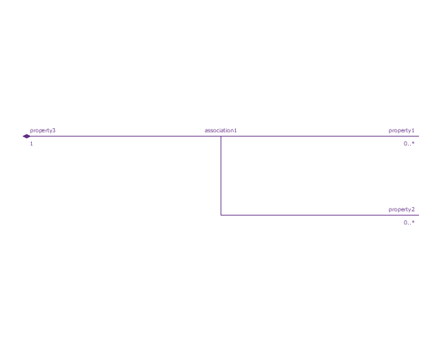
Part association
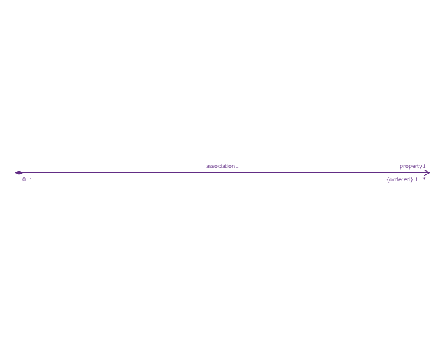
Part association 2
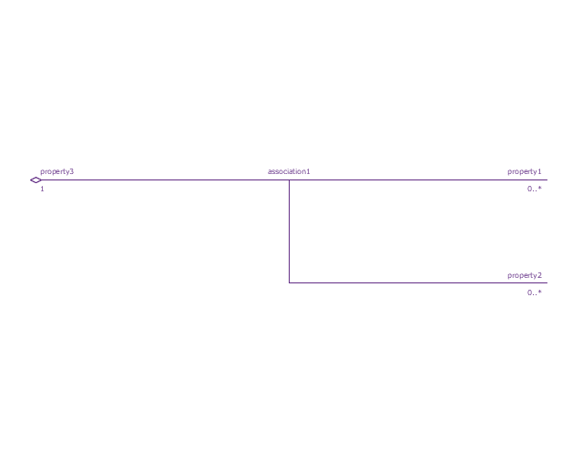
Shared association
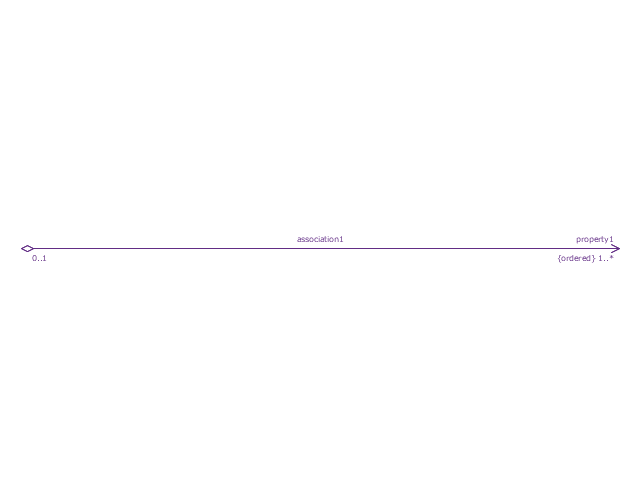
Shared association 2

Multibranch part association
Multibranch shared association
Generalization

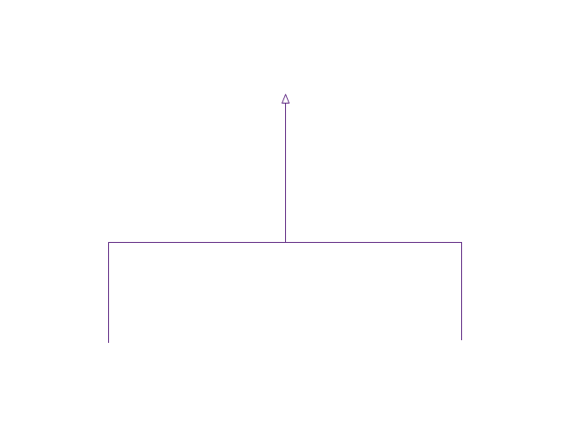
Multibranch generalization
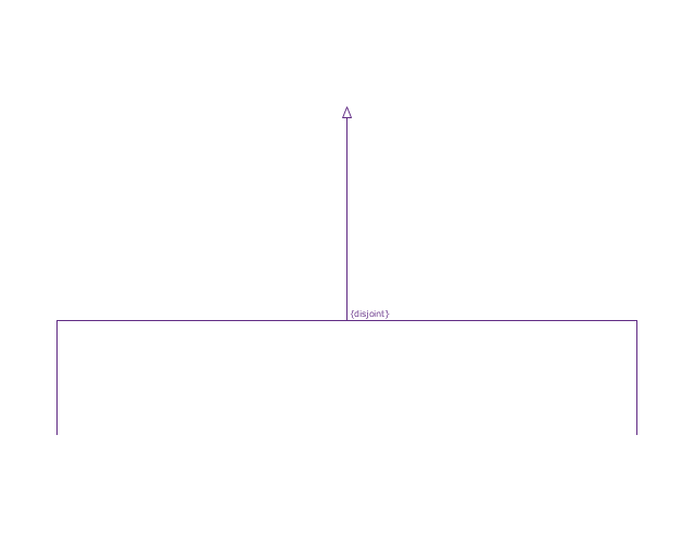
Generalization set, disjoint
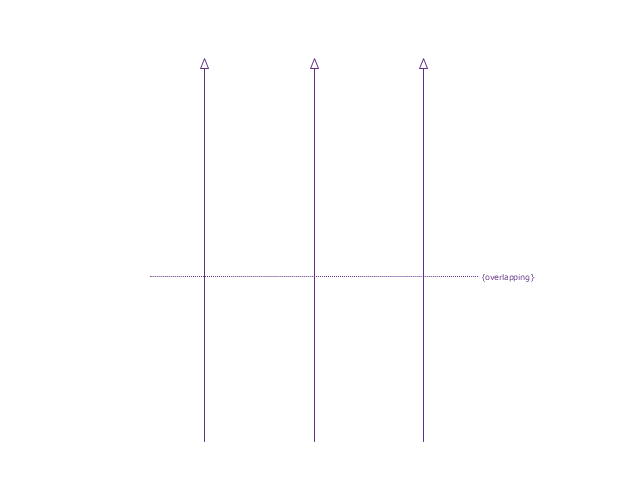
Generalization set, overlapping
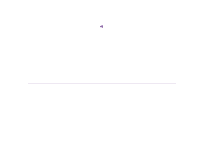
Block namespace containment
Participant property
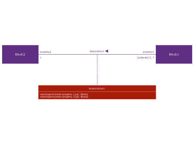
Participant property 2
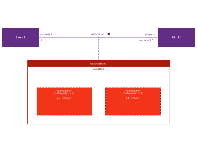
Participant property 3
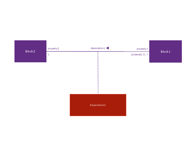
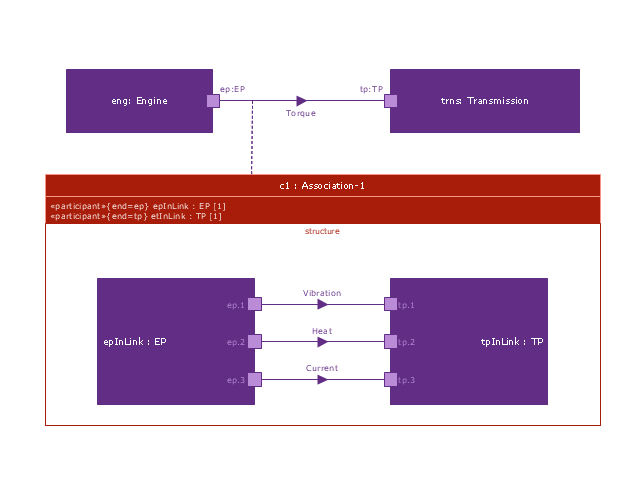
Connector property
Conjugated ports

Conjugated ports 2

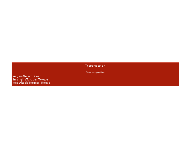
Ports with flow properties

Port (compartment notation)
-vector-stencils-library---block-definition-diagram.png--diagram-flowchart-example.png)
Port (nested)
-vector-stencils-library---block-definition-diagram.png--diagram-flowchart-example.png)
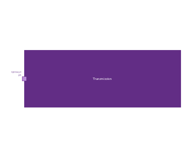
Proxy port
Full port

Flow property
Required and provided features
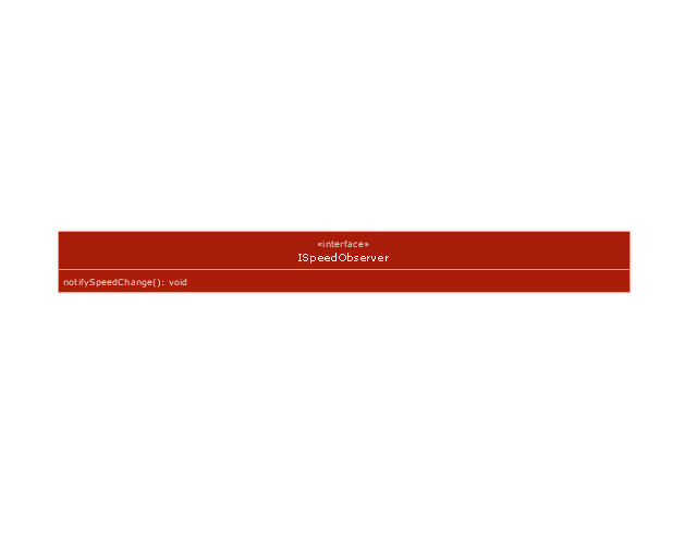
Interface block

Item flow
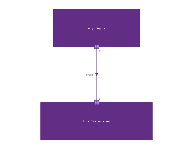
Item flow 2
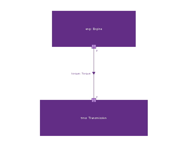
Item flow 3
Interface
Required and provided interfaces

Required and provided interfaces 2
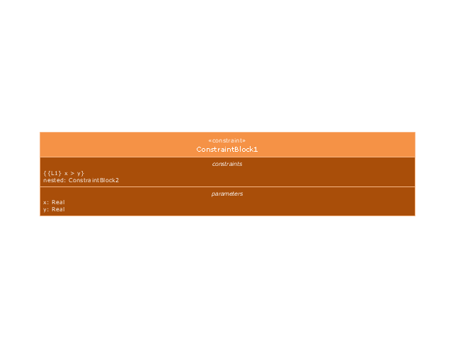
Constraint block
Financial Trade UML Use Case Diagram Example

This sample shows the work of the Financial Trade sphere and can be used by trading companies, commercial organizations, traders, different exchanges.
UML Block Diagram

This sample shows the work of the taxi service and is used by taxi stations, by airports, in the tourism field and delivery service.
Use Case Diagrams technology with ConceptDraw PRO

This vector stencils library contains 10 SysML symbols.
Use it to design your use case diagrams using ConceptDraw PRO diagramming and vector drawing software.
"A use case diagram at its simplest is a representation of a user's interaction with the system that shows the relationship between the user and the different use cases in which the user is involved. A use case diagram can identify the different types of users of a system and the different use cases and will often be accompanied by other types of diagrams as well." [Use case diagram. Wikipedia]
The vector stencils library "Use case diagram" is included in the SysML solution from the Software Development area of ConceptDraw Solution Park.
Use case
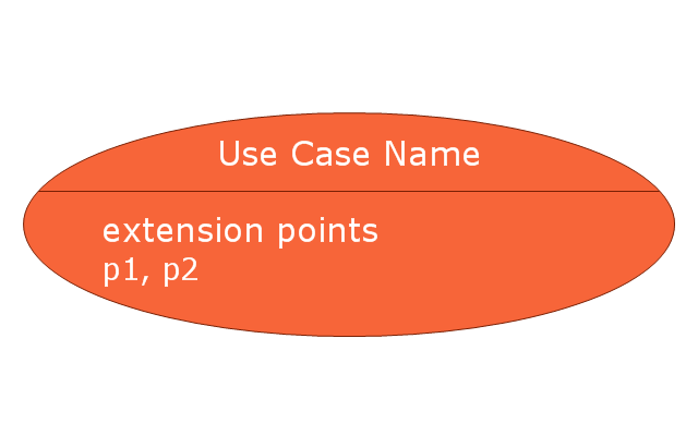
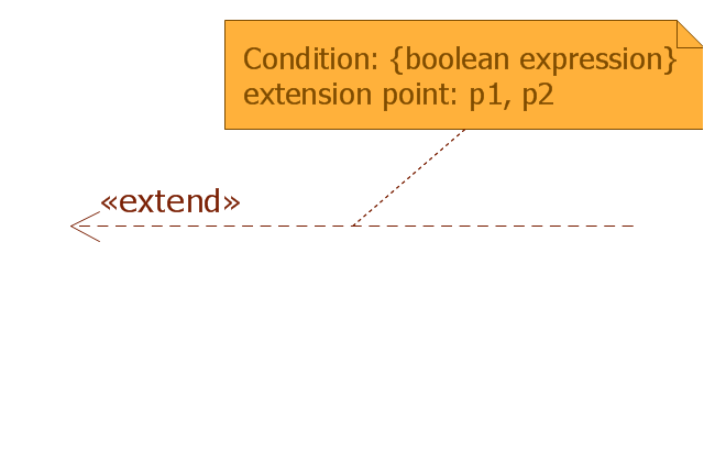
Use case with extension points
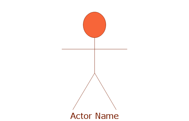
Actor
Actor 2

Subject

Communication path

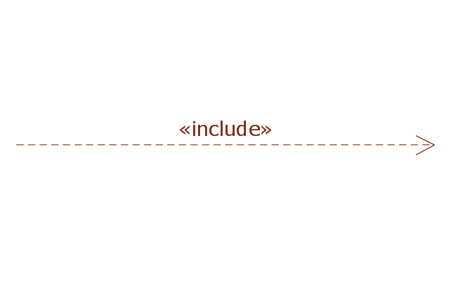
Include
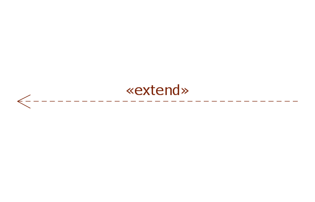
Extend
Extend with condition
Generalization

UML Class Diagram. Design Elements

UML Use Case Diagram. Design Elements
")

This example of UML class diagram models bank account system.
"A bank account is a financial account between a bank customer and a financial institution. A bank account can be a deposit account, a credit card, or any other type of account offered by a financial institution. The financial transactions which have occurred within a given period of time on a bank account are reported to the customer on a bank statement and the balance of the account at any point in time is the financial position of the customer with the institution. a fund that a customer has entrusted to a bank and from which the customer can make withdrawals." [Bank account. Wikipedia]
This bank account system UML class diagram example was created using the ConceptDraw PRO diagramming and vector drawing software extended with the ATM UML Diagrams solution from the Software Development area of ConceptDraw Solution Park.
UML class diagram of bank account system

This bank account UML package diagram was redesigned from the Wikimedia Commons file: Package diagram1.jpg.
[commons.wikimedia.org/ wiki/ File:Package_ diagram1.jpg]
This file is licensed under the Creative Commons Attribution-Share Alike 3.0 Unported license. [creativecommons.org/ licenses/ by-sa/ 3.0/ deed.en]
"A very important concept in object-oriented design, inheritance, refers to the ability of one class (child class) to inherit the identical functionality of another class (super class), and then add new functionality of its own. (In a very non-technical sense, imagine that I inherited my mother's general musical abilities, but in my family I'm the only one who plays electric guitar.) To model inheritance on a class diagram, a solid line is drawn from the child class (the class inheriting the behavior) with a closed, unfilled arrowhead (or triangle) pointing to the super class. Consider types of bank accounts: Figure 4 shows how both CheckingAccount and SavingsAccount classes inherit from the BankAccount class.
Figure 4: Inheritance is indicated by a solid line with a closed, unfilled arrowhead pointing at the super class." [ibm.com/ developerworks/ rational/ library/ content/ RationalEdge/ sep04/ bell/ index.html]
This bank account UML package diagram example was created using the ConceptDraw PRO diagramming and vector drawing software extended with the ATM UML Diagrams solution from the Software Development area of ConceptDraw Solution Park.
Bank account UML package diagram

UML in 10 mins

This sample describes the credit card processing system. It’s a UML Class Diagram with generalization sets. This sample can be used by the banks, business and financial companies, exchanges.
OMT Method

All diagrams produced with ConceptDraw PRO are vector graphic documents and are available for reviewing, modifying, and converting to a variety of formats (image, HTML, PDF file, MS PowerPoint Presentation, Adobe Flash or MS Visio XML).
This example of UML class diagram models bank account system.
"A bank account is a financial account between a bank customer and a financial institution. A bank account can be a deposit account, a credit card, or any other type of account offered by a financial institution. The financial transactions which have occurred within a given period of time on a bank account are reported to the customer on a bank statement and the balance of the account at any point in time is the financial position of the customer with the institution. a fund that a customer has entrusted to a bank and from which the customer can make withdrawals." [Bank account. Wikipedia]
This bank account system UML class diagram example was created using the ConceptDraw PRO diagramming and vector drawing software extended with the ATM UML Diagrams solution from the Software Development area of ConceptDraw Solution Park.
"A bank account is a financial account between a bank customer and a financial institution. A bank account can be a deposit account, a credit card, or any other type of account offered by a financial institution. The financial transactions which have occurred within a given period of time on a bank account are reported to the customer on a bank statement and the balance of the account at any point in time is the financial position of the customer with the institution. a fund that a customer has entrusted to a bank and from which the customer can make withdrawals." [Bank account. Wikipedia]
This bank account system UML class diagram example was created using the ConceptDraw PRO diagramming and vector drawing software extended with the ATM UML Diagrams solution from the Software Development area of ConceptDraw Solution Park.
UML class diagram of bank account system
UML Package Diagram. Design Elements

ConceptDraw has 393 vector stencils in the 13 libraries that helps you to start using software for designing your own UML Diagrams. You can use the appropriate stencils of UML notation from UML Package library.
UML Deployment Diagram. Design Elements

ConceptDraw has 393 vector stencils in the 13 libraries that helps you to start using software for designing your own UML Diagrams. You can use the appropriate stencils of UML notation from UML Deployment library.
UML Composite Structure Diagram. Design Elements

ConceptDraw has 393 vector stencils in the 13 libraries that helps you to start using software for designing your own UML Diagrams. You can use the appropriate stencils of UML notation from UML Composite Structure library.
UML Object Diagram. Design Elements

ConceptDraw has 393 vector stencils in the 13 libraries that helps you to start using software for designing your own UML Diagrams. You can use the appropriate stencils of UML notation from UML Object library.
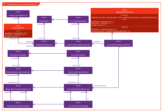
This example was drawn on the base of figure 1 on the webpage "Template: OASIS:FunctionalBreakdownStructure" from the OASIS website.
"The FunctionalBreakdownStructure template describes how to represent a relationship between a FunctionalElementDefinition and another FunctionalElementDefinition that is a constituent.
The SysML Block Definition diagram in Figure 1 shows how a functional breakdown is represented in the PLCS PSM."
[docs.oasis-open.org/ plcs/ plcslib/ v1.0/ csprd01/ data/ contexts/ OASIS/ templates/ FunctionalBreakdownStructure/ template.html]
"A block definition diagram is based on the UML class diagram, with restrictions and extensions as defined by SysML." [omg.org/ spec/ SysML/ 1.3/ PDF]
The example "SysML block definition diagram - Function Breakdown model" was drawn using the ConceptDraw PRO diagramming and vector drawing software extended with the SysML solution from the Software Development area of ConceptDraw Solution Park.
Example of SysML BDD
About UML

This sample shows the work of the taxi service and is used by taxi stations, by airports, in the tourism field and delivery service.
- UML Class Diagram Generalization Example | Rapid UML | UML ...
- UML Class Diagram Generalization Example | UML Sample Project ...
- Class Diagram Tool | UML Class Diagram Generalization Example ...
- Cross-Functional Flowcharts | UML Class Diagram Generalization ...
- UML Class Diagram Generalization Example | UML Class Diagram ...
- Example Of Generalization For Class Diagram
- UML Class Diagram Generalization Example
- What Is Generalization In Class Diagram
- UML Deployment Diagram Example - ATM System | UML Class ...
- UML Class Diagram Generalization Example | Financial Trade UML ...
- UML Activity Diagram | UML Class Diagram Generalization Example ...
- UML Class Diagram Generalization Example | Class Diagram ...
- UML Class Diagram Generalization Example
- UML Class Diagram Generalization Example | Vector stencils library ...
- UML Class Diagram Generalization Example | UML Class Diagrams ...
- UML Class Diagram Generalization Example
- UML Diagram | UML Class Diagram Generalization Example ...
- Rapid UML | UML Class Diagram Generalization Example ...
- UML Diagrams with ConceptDraw PRO | UML Class Diagram ...
- UML Class Diagram Generalization Example | Overlapping In ...