How To use House Electrical Plan Software


The vector stencils library "Lighting" contains 55 symbols of lighting devices and equipment.
Use these shapes for drawing lighting design floor plans, circuit schematic and wiring diagrams, cabling layouts, and reflected ceiling plans in the ConceptDraw PRO diagramming and vector drawing software.
The vector stencils library "Lighting" is included in the Electric and Telecom Plans solution from the Building Plans area of ConceptDraw Solution Park.
Luminaire ceiling mount

Enclosed ceiling luminaire

Wall light

Down lighter

Outdoor lightning

Outdoor lightning, bollard

1-light bar

2-light bar

4-light bar

6-light bar

8-light bar

Batten fluorescent, 1 lamp

Batten fluorescent, 2 lamps

Batten fluorescent, 3 lamps

Batten fluorescent, 4 lamps

Surface Fluorescent Light

Modular fluorescent fitting

Modular fluorescent fitting, inverter

Modular fluorescent fitting 2

Emergency light

Emergency light 2

Emergency sign

Emergency Light, Recessed

Light, Surface Mounted

Ceiling Light Outlet

Recessed Ceiling Light

Ceiling Fan

Ceiling Light with Pull Cord

Weatherproof Landscape Light

Wall Light Outlet

Control Keypad

Emergency Battery Unit

Emergency Battery Unit with two Lights

Emergency Single Light, Remote Mounted

Emergency Duplex Light, Remote Mounted

Spotlight, Single Head

Spotlight, Double Head

Exit Sign, Pendant Mounted

Exit Sign, Wall Mounted

Light, Pole Mounted

Light Flood, Pole Mounted

Light Flood, Wall Mounted

Light, Stanchion Mounted

Twin Lights, Pendant Mounted

Inground Light, Floor Mounted

Suspended Light

Suspended Lights

Integrated Light

Lights, Track Mounted

Night Light

Roadway Light, Cobra Head

Louvers

Light, Directional Accent

Light, Directional Aiming Line

Light, Directional Arrow
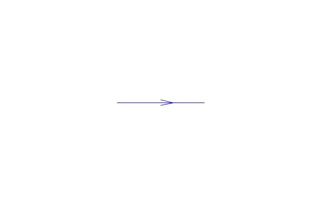
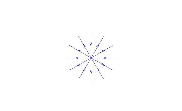
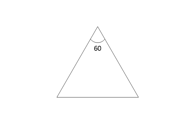
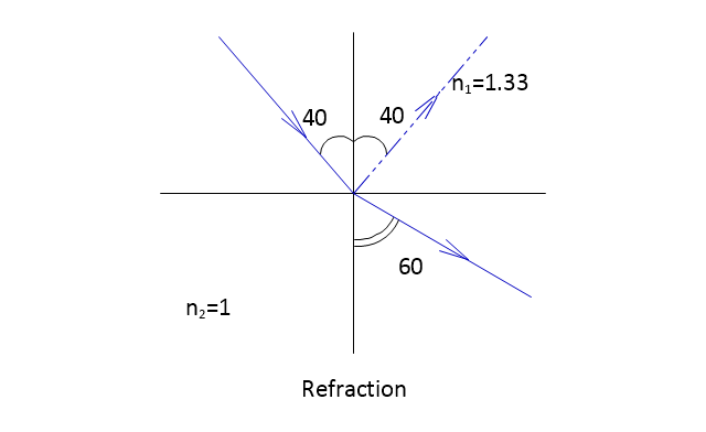
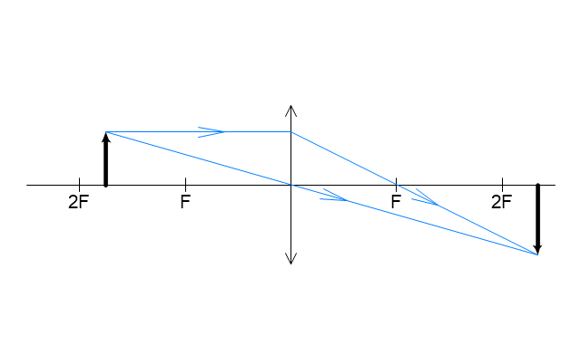
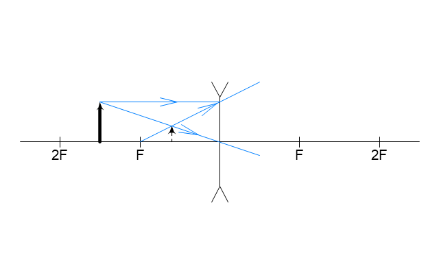
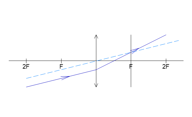
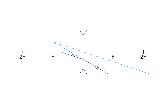
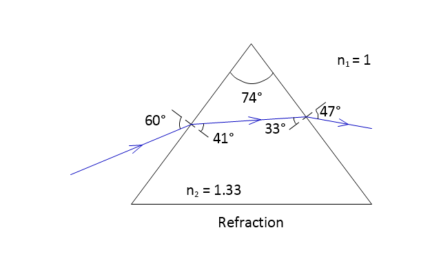
The vector stencils library "Optics" contains 17 symbol icons: reflecting surface; convex and concave lens with and without optic axis, body or ray; ray; parallel beam of light; point light source; prism with and without ray path; refraction.
Use these shapes for drawing schemes of physical experiments in geometrical optics and ray tracing diagrams.
"Geometrical optics, or ray optics, describes light propagation in terms of "rays". The "ray" in geometric optics is an abstraction, or "instrument", which can be used to approximately model how light will propagate. Light rays are defined to propagate in a rectilinear path as they travel in a homogeneous medium. Rays bend (and may split in two) at the interface between two dissimilar media, may curve in a medium where the refractive index changes, and may be absorbed and reflected. Geometrical optics provides rules, which may depend on the color (wavelength) of the ray, for propagating these rays through an optical system. This is a significant simplification of optics that fails to account for optical effects such as diffraction and interference. It is an excellent approximation, however, when the wavelength is very small compared with the size of structures with which the light interacts. Geometric optics can be used to describe the geometrical aspects of imaging, including optical aberrations." [Geometrical optics. Wikipedia]
The example "Design elements - Optics" was created using the ConceptDraw PRO diagramming and vector drawing software extended with the Physics solution from the Science and Education area of ConceptDraw Solution Park.
Optical symbols
Electrical Symbols, Electrical Diagram Symbols

The vector stencils library "Optics" contains 17 symbol icons: reflecting surface; convex and concave lens with and without optic axis, body or ray; ray; parallel beam of light; point light source; prism with and without ray path; refraction.
Use these shapes for drawing physical schemes of geometrical optics experiments and ray tracing diagrams in the ConceptDraw PRO diagramming and vector drawing software extended with the Physics solution from the Science and Education area of ConceptDraw Solution Park.
www.conceptdraw.com/ solution-park/ science-education-physics
Reflecting Surface

Convex Lens
Concave Lens
Object
Ray
Point Light Source
Prism
Refraction
Body and Convex Lens
Body and concave lens
Convex Lens and Ray
Concave Lens and Ray
Ray path through prism
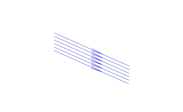
Parallel beam of light
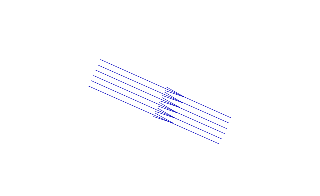
Parallel beam of light 2
Concave lens, optic axis
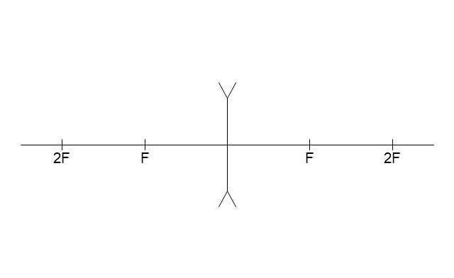
Convex lens, optic axis

How To use Electrical and Telecom Plan Software


The vector stencils library "HVAC controls" contains 23 symbols of HVAC controls (sensors, actuators, timers, controllers, I/ O points). Use it for drawing HVAC system diagrams, controls drawings, and automated building control and environmental control systems design. The example "HVAC controls - Vector stencils library" was created using the ConceptDraw PRO diagramming and vector drawing software extended with the HVAC Plans solution from the Building Plans area of ConceptDraw Solution Park.
Temperature sensor

Humidity sensor

Enthalpy sensor

Pressure sensor

Flow sensor

Velocity sensor

Voltage sensor

General purpose sensor

Light sensor

Rotation sensor

Vibration sensor

Timer

Current sensor

Power sensor

Air quality sensor

Level

End switch

Smoke detector

Power connection

Actuator

I/O point

Label

Wire note

Electrical Drawing Software and Electrical Symbols

The vector stencils library "Electrical and telecom" contains 83 symbols of electrical and telecommunication equipment.
Use these shapes for drawing electrical and telecom system design floor plans, cabling layout schemes, and wiring diagrams in the ConceptDraw PRO diagramming and vector drawing software.
The vector stencils library "Electrical and telecom" is included in the Electric and Telecom Plans solution from the Building Plans area of ConceptDraw Solution Park.
Luminaire ceiling mount

Enclosed ceiling luminaire

Wall light

1-light bar

2-light bar

4-light bar

6-light bar

8-light bar

Down lighter

Outdoor lightning

Outdoor lightning, bollard

Batten fluorescent, 1 lamp

Batten fluorescent, 2 lamps

Batten fluorescent, 3 lamps

Batten fluorescent, 4 lamps

Surface Fluorescent Light

Modular fluorescent fitting

Modular fluorescent fitting, inverter

Modular fluorescent fitting 2

Pull-cord switch

Emergency light

Emergency light 2

Emergency sign

Switch

Switch, 1 pole

Switch, 2 pole

Switch, 2-way

Multi-switch

Switch, intermediate

Dimmer switch

Dimmer switch 2

Socket

Socket 2

Switched socket

Switched socket 2

Double socket

Double socket 2

Socket outlet

Telephone outlet

Telephone outlet 2

Stereo outlet

Television outlet

Service panel, surface

Service panel, inset

Thermostat

Ceiling fan

Hold open unit

Detector

Fire alarm

City Fire Alarm Station

Fire Alarm Station

Fire Alarm Bell

Fire Alarm Central Station

Automatic Fire Alarm Device

Main control

Ground

Doorbell

Push Button

Buzzer

Annunciator

Horn

Maid's Signal Plug

Signal Central Station

Doorbell Chime

Doorbell Transformer

Magnetic Door Hold

Intercom

Telephone Key System

Digital Satellite System

Inside Antenna

Outside Antenna

Electric Motors

Single Phase

Three of Poly Phase

Wall Mounted Electrical Junction Box for Hardware

Wall Mounted Telephone/Data Junction Box for Hardware

Card Reader Access System

Emergency Release Button

Motion Sensor

Electric Door Opener

Watchman's Station

Watchman's Central Station

Battery

Electrical Symbols — Terminals and Connectors

Interior Design. Site Plan — Design Elements

Wiring Diagrams with ConceptDraw DIAGRAM

The vector stencils library "Switches and relays" contains 58 symbols of electrical contacts, switches, relays, circuit breakers, selectors, connectors, disconnect devices, switching circuits, current regulators, and thermostats for electrical devices.
"In electrical engineering, a switch is an electrical component that can break an electrical circuit, interrupting the current or diverting it from one conductor to another.
The most familiar form of switch is a manually operated electromechanical device with one or more sets of electrical contacts, which are connected to external circuits. Each set of contacts can be in one of two states: either "closed" meaning the contacts are touching and electricity can flow between them, or "open", meaning the contacts are separated and the switch is nonconducting. The mechanism actuating the transition between these two states (open or closed) can be either a "toggle" (flip switch for continuous "on" or "off") or "momentary" (push-for "on" or push-for "off") type.
A switch may be directly manipulated by a human as a control signal to a system, such as a computer keyboard button, or to control power flow in a circuit, such as a light switch. Automatically operated switches can be used to control the motions of machines, for example, to indicate that a garage door has reached its full open position or that a machine tool is in a position to accept another workpiece. Switches may be operated by process variables such as pressure, temperature, flow, current, voltage, and force, acting as sensors in a process and used to automatically control a system. ... A switch that is operated by another electrical circuit is called a relay. Large switches may be remotely operated by a motor drive mechanism. Some switches are used to isolate electric power from a system, providing a visible point of isolation that can be padlocked if necessary to prevent accidental operation of a machine during maintenance, or to prevent electric shock." [Switch. Wikipedia]
"A relay is an electrically operated switch. Many relays use an electromagnet to mechanically operate a switch, but other operating principles are also used, such as solid-state relays. Relays are used where it is necessary to control a circuit by a low-power signal (with complete electrical isolation between control and controlled circuits), or where several circuits must be controlled by one signal. The first relays were used in long distance telegraph circuits as amplifiers: they repeated the signal coming in from one circuit and re-transmitted it on another circuit. Relays were used extensively in telephone exchanges and early computers to perform logical operations.
A type of relay that can handle the high power required to directly control an electric motor or other loads is called a contactor. Solid-state relays control power circuits with no moving parts, instead using a semiconductor device to perform switching. Relays with calibrated operating characteristics and sometimes multiple operating coils are used to protect electrical circuits from overload or faults; in modern electric power systems these functions are performed by digital instruments still called "protective relays"." [Relay. Wikipedia]
The shapes example "Design elements - Switches and relays" was drawn using the ConceptDraw PRO diagramming and vector drawing software extended with the Electrical Engineering solution from the Engineering area of ConceptDraw Solution Park.
Switch and relay symbols

This vector stencils library contains 195 cloud computing icons.
Use it to design cloud computing infographic and diagrams with ConceptDraw PRO software.
"Cloud computing, also on-demand computing, is a kind of Internet-based computing that provides shared processing resources and data to computers and other devices on demand. It is a model for enabling ubiquitous, on-demand access to a shared pool of configurable computing resources (e.g., networks, servers, storage, applications and services), which can be rapidly provisioned and released with minimal management effort. Cloud computing and storage solutions provide users and enterprises with various capabilities to store and process their data in third-party data centers.
Cloud computing has become a highly demanded service or utility due to the advantages of high computing power, cheap cost of services, high performance, scalability, accessibility as well as availability." [Cloud computing. Wikipedia]
The vector stencils library "Cloud clipart" is included in the Cloud Computing Diagrams solution from the Computer and Networks area of ConceptDraw Solution Park.
Access point
Airport

Alert

Banknote

Banknote bundle
Banknote bundles
Backup
Bar chart

Big data

Book (closed)
-cloud-clipart---vector-stencils-library.png--diagram-flowchart-example.png)
Book (open)
-cloud-clipart---vector-stencils-library.png--diagram-flowchart-example.png)
Books

Box, close

Box, open

Braces
Brackets

Bug

Building

Bus

Cable connection
Calculator
Calendar

Car
CD/DVD
Check list

Check mark

Clock
Cloud

Cloud computing
Cloud database

Cloud hosting

Cloud storage

Code
Coffee cup

Coin

Coins stack
Coins stacks
Communication

Computer terminal
Console

CPU
Credit card

Cubes
Dashboard

Database
Databases

Datacenter
Dialog box
Dialog boxes

Document
Documents

Dollar sign

Download

Earth

Email

Equal sign
Ethernet jack
Ethernet plug
Euro sign

Exclamation mark

Eye
Feed symbol

Feedback

File

Files

Filter

Firewall
Flash drive

Folder

Folders

Gamepad

Gauge
Gear
Gears, 2
Gears, 3
Globe

Hacker

Hard drive

Heart

Heart rhythm

Home

Hosting
Hotel

House

Image

Info

IP phone
Jet

Key

Keyboard
Laptop

Lego
Letter

Light bulb

Lightning
Line chart
Linux penguin

List

Load balancer
Location mark

Lock, close

Lock, open

Lock and key

Log
Login

Logout

Magnifying glass

Mail

Map

Memory (RAM)
-cloud-clipart---vector-stencils-library.png--diagram-flowchart-example.png)
Microphone

Minus sign
Mobile phone
Monitor

Mouse
Movie

Music

Music player

Network
Network bus

Newspaper

NIC (Network interface controller)
-cloud-clipart---vector-stencils-library.png--diagram-flowchart-example.png)
Not found (Error 404)
-cloud-clipart---vector-stencils-library.png--diagram-flowchart-example.png)
Notebook
Office printer
Operator

Page
Pages

PC

Pencil

Photo

Photo camera
Pie chart

Platform
Plus sign

Pound sign

Printer
Puzzle

Puzzles, 2x2
Puzzles, 3x3
Question sign

Rackmount server
Router
Safe

Satellite

Satellite antenna
Schedule

Sensor
Server
Server rack
Shield
Ship
Shopping bag

Shopping basket

Shopping cart

Sign up

Smartphone
Social network
Software box
Sound

Spider

Spreadsheet
SSD
Star

Stars, 5

Stethoscope

Stickman
Stickmen

Suitcase

Support
Switch
Syringe
Tablet computer
Tools
Train
Truck

Truck 2

TV

Umbrella
Upload

User man

User woman

User profile

Video

Video camera

Video mail

Virtual disk

Virus

Wallet

Web camera

Wifi antenna
Wireless
Wrench

X cross symbol

Yen sign

Cisco Products Additional. Cisco icons, shapes, stencils and symbols

Mechanical Drawing Symbols

Building Drawing. Design Element Site Plan

Process Flow Diagram Symbols

The vector stencils library "Switches" contains 25 symbols of electrical and light switches and breakers.
"In electrical engineering, a switch is an electrical component that can break an electrical circuit, interrupting the current or diverting it from one conductor to another.
The most familiar form of switch is a manually operated electromechanical device with one or more sets of electrical contacts, which are connected to external circuits.
A switch may be directly manipulated by a human as a control signal to a system, ... or to control power flow in a circuit, such as a light switch. Automatically operated switches can be used to control the motions of machines, for example, to indicate that a garage door has reached its full open position or that a machine tool is in a position to accept another workpiece. Switches may be operated by process variables such as pressure, temperature, flow, current, voltage, and force, acting as sensors in a process and used to automatically control a system. For example, a thermostat is a temperature-operated switch used to control a heating process. A switch that is operated by another electrical circuit is called a relay." [Switch. Wikipedia]
Use the design elements library "Switches" for drawing light switches layouts, electrical and telecommunication equipment floor plans for building design and construction using the ConceptDraw PRO diagramming and vector drawing software.
The shapes library "Switches" is included in the Electric and Telecom Plans solution from the Building Plans area of ConceptDraw Solution Park.
Electrical switch symbols

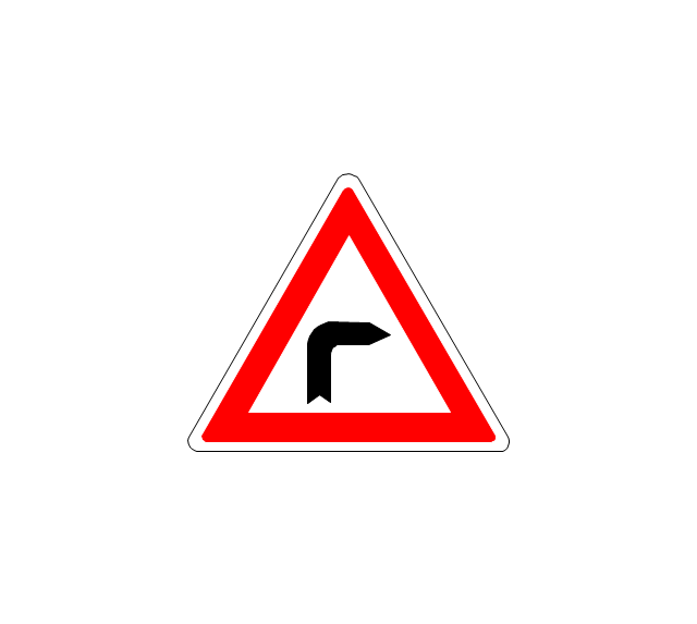
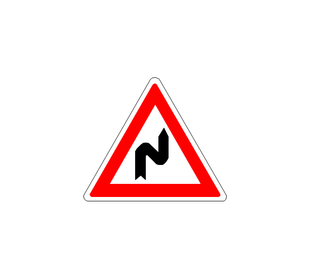
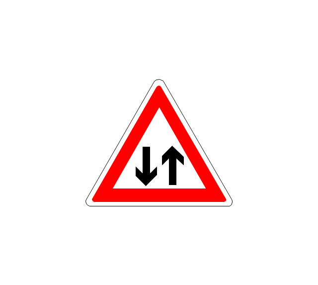
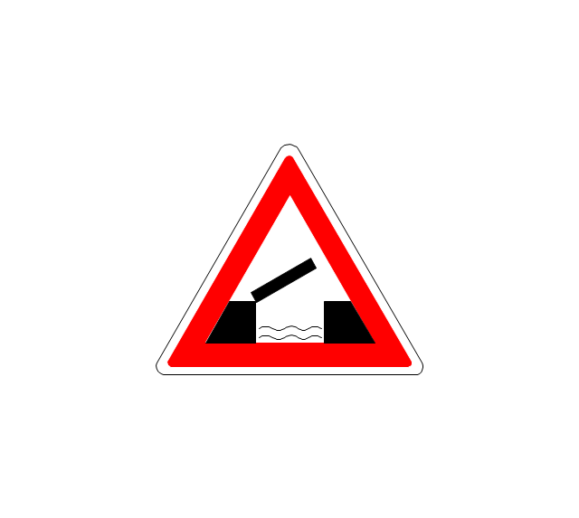
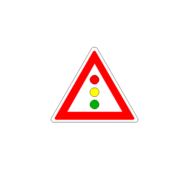
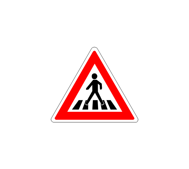
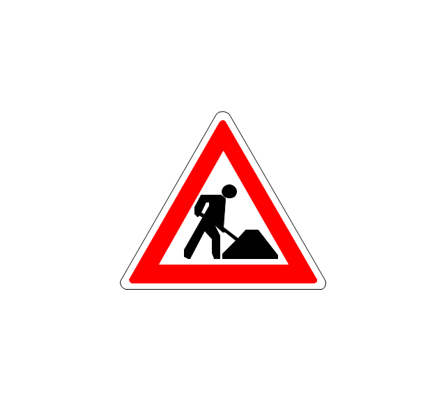
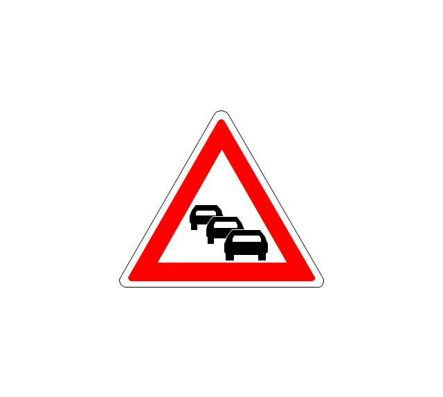
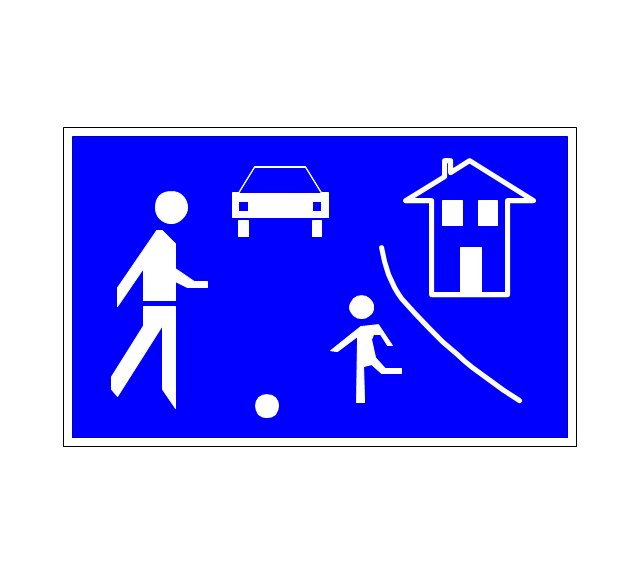
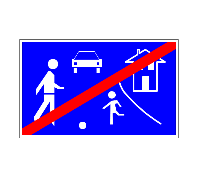
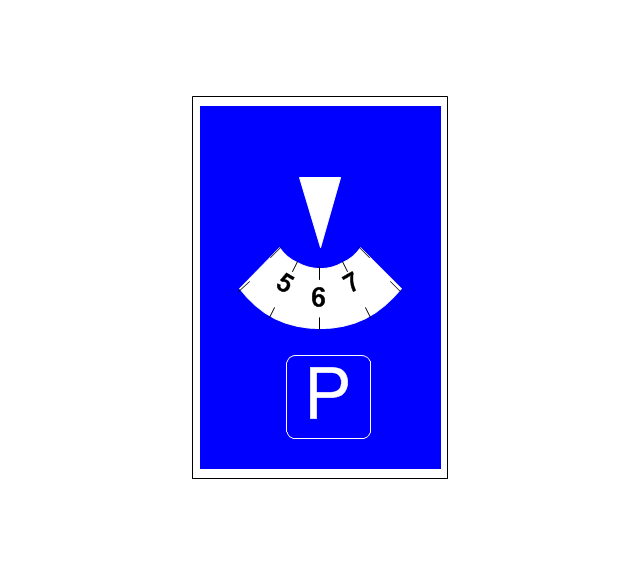
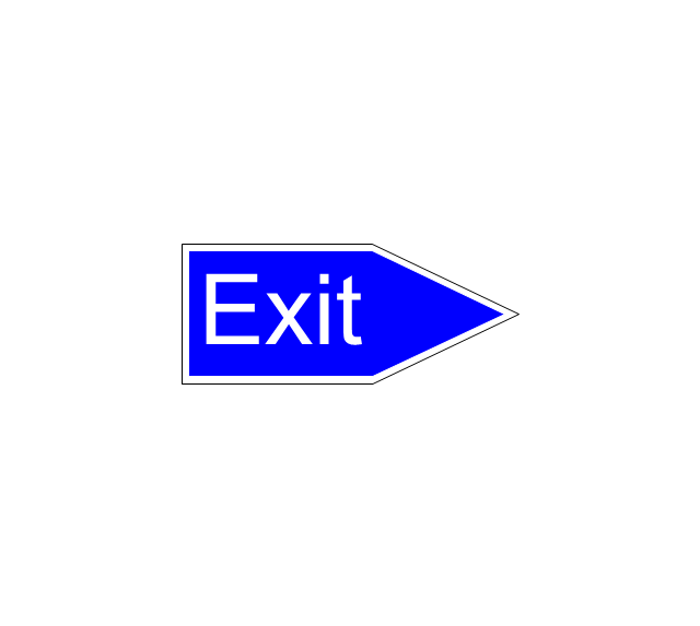
The vector stencils library "Road signs" contains 58 symbols of road signs for labeling the road and route maps, directional and transit maps, street and locator maps.
"Traffic signs or road signs are signs erected at the side of or above roads to give instructions or provide information to road users.
... many countries have adopted pictorial signs or otherwise simplified and standardized their signs to overcome language barriers, and enhance traffic safety. Such pictorial signs use symbols (often silhouettes) in place of words and are usually based on international protocols. Such signs were first developed in Europe, and have been adopted by most countries to varying degrees." [Traffic sign. Wikipedia]
The pictograms example "Road signs - Vector stencils library" was created using the ConceptDraw PRO diagramming and vector drawing software extended with the Directional Maps solution from the Maps area of ConceptDraw Solution Park.
www.conceptdraw.com/ solution-park/ maps-directional
Danger place
Intersection
Intersection 2
Bend
Double bend
Two-way traffic
Mobile bridge
Light signal
Pedestrian crossing
Road work
Back-up
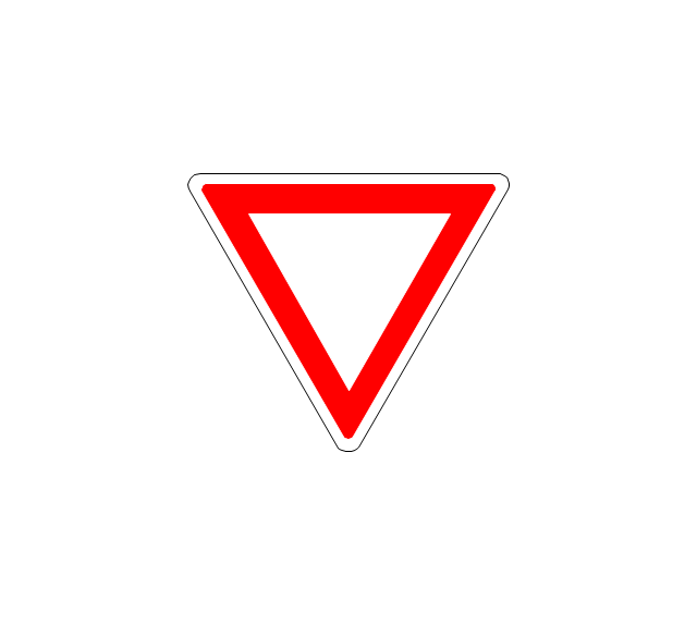
Give way
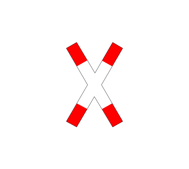
Crossing
Stop

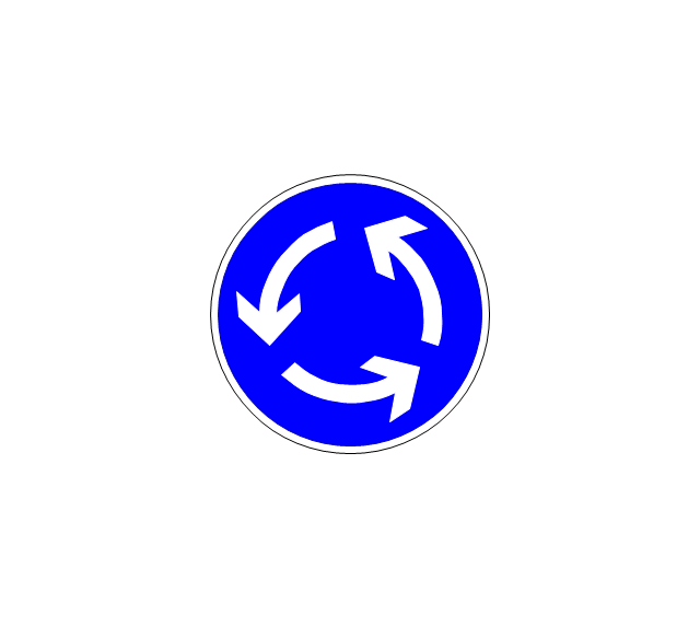
Roundabout
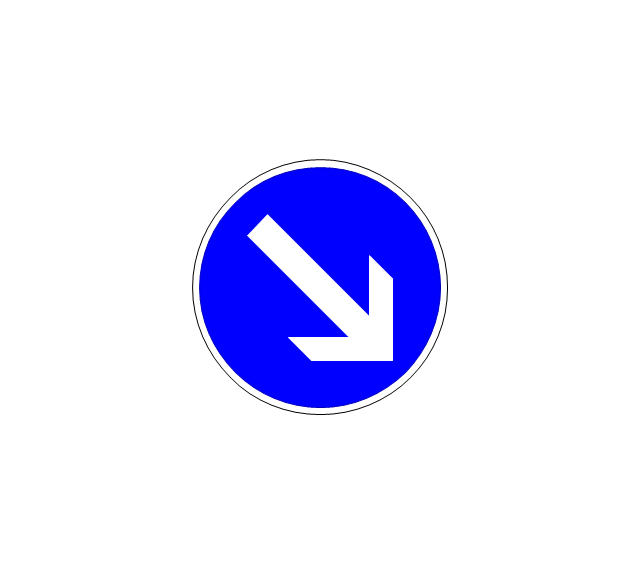
Pass this side
Direction to be followed
One-way street
Cycle track
No entry
No entry both directions

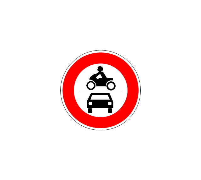
No power vehicles
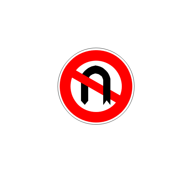
No U-turns
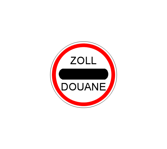
No passing without stopping
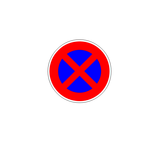
No standing and parking
No parking
Speed limit
Height limit
Width limit
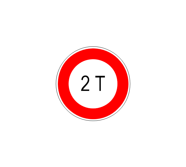
Weight limit
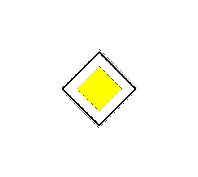
Priority over oncoming traffic
Streetcar or regular buses

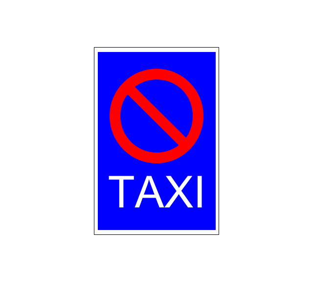
Taxi status
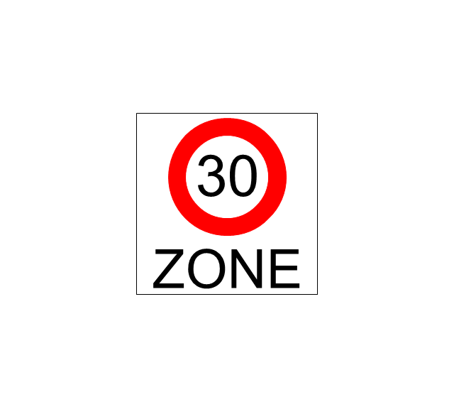
Beginning that speed 30-Zone
End that speed 30-Zone
Pedestrian crossing 2
Police
Hotel
Breakdown service
Restaurant
P + R
Restroom
Fuel
Telephone
Recommended speed
Nodal point of a motorwa
Parking
Dead end
Motorway
End motorway
Populated zone
End populated zone
Parking with clock
Number sign (motorway)
-road-signs---vector-stencils-library.png--diagram-flowchart-example.png)
Exit
Direction to place
Board of announcement of exit
Number sign (federal highway)
-road-signs---vector-stencils-library.png--diagram-flowchart-example.png)
- Symbol Of Electrical Wiring Wall Bracket
- Lighting - Vector stencils library | Lighting Point Symbol
- Light Points Symbol On Drawing
- Symbols For Electrical Lighting Point
- Lighting - Vector stencils library | Lighing Point Circuit Symbol
- Lighting Layout Symbols
- Electrical Main Control Intake Point Symbol
- Symbol Of Ceiling Point Lighting
- Electrical Symbol For Ligthing Point
- Intake Point Symbol
- Electrical Symbols , Electrical Diagram Symbols | How To use House ...
- Symbol Of Main Control Or Intake Point
- Lighting - Vector stencils library | Design elements - Lighting ...
- Pendant Light Symbol
- Wall Mounted Fan Point Electrical Layout Symbol
- Lighting - Vector stencils library | Electrical and telecom - Vector ...
- Cad Electrical Symbols For Wall Bracket Socket Light Point Switches
- Fluorescent Lamp Symbol
- Drawing Of Lamp In Floor Plan
- Symbol Of Ray Of Light