Electrical Symbols, Electrical Diagram Symbols

How To use House Electrical Plan Software


The vector stencils library "Electrical and telecom" contains 83 symbols of electrical and telecommunication equipment.
Use these shapes for drawing electrical and telecom system design floor plans, cabling layout schemes, and wiring diagrams in the ConceptDraw PRO diagramming and vector drawing software.
The vector stencils library "Electrical and telecom" is included in the Electric and Telecom Plans solution from the Building Plans area of ConceptDraw Solution Park.
Luminaire ceiling mount

Enclosed ceiling luminaire

Wall light

1-light bar

2-light bar

4-light bar

6-light bar

8-light bar

Down lighter

Outdoor lightning

Outdoor lightning, bollard

Batten fluorescent, 1 lamp

Batten fluorescent, 2 lamps

Batten fluorescent, 3 lamps

Batten fluorescent, 4 lamps

Surface Fluorescent Light

Modular fluorescent fitting

Modular fluorescent fitting, inverter

Modular fluorescent fitting 2

Pull-cord switch

Emergency light

Emergency light 2

Emergency sign

Switch

Switch, 1 pole

Switch, 2 pole

Switch, 2-way

Multi-switch

Switch, intermediate

Dimmer switch

Dimmer switch 2

Socket

Socket 2

Switched socket

Switched socket 2

Double socket

Double socket 2

Socket outlet

Telephone outlet

Telephone outlet 2

Stereo outlet

Television outlet

Service panel, surface

Service panel, inset

Thermostat

Ceiling fan

Hold open unit

Detector

Fire alarm

City Fire Alarm Station

Fire Alarm Station

Fire Alarm Bell

Fire Alarm Central Station

Automatic Fire Alarm Device

Main control

Ground

Doorbell

Push Button

Buzzer

Annunciator

Horn

Maid's Signal Plug

Signal Central Station

Doorbell Chime

Doorbell Transformer

Magnetic Door Hold

Intercom

Telephone Key System

Digital Satellite System

Inside Antenna

Outside Antenna

Electric Motors

Single Phase

Three of Poly Phase

Wall Mounted Electrical Junction Box for Hardware

Wall Mounted Telephone/Data Junction Box for Hardware

Card Reader Access System

Emergency Release Button

Motion Sensor

Electric Door Opener

Watchman's Station

Watchman's Central Station

Battery

Flow chart Example. Warehouse Flowchart


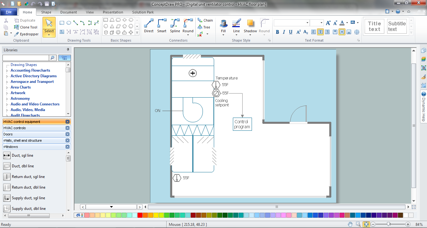
 HVAC Plans
Use HVAC Plans solution to create professional, clear and vivid HVAC-systems design plans, which represent effectively your HVAC marketing plan ideas, develop plans for modern ventilation units, central air heaters, to display the refrigeration systems for automated buildings control, environmental control, and energy systems.
This electrical floot plan sample shows the Power socket outlet layout.
"The term plug is in general and technical use in all forms of English, common alternatives being power plug, electric plug, and (in the UK) plug top. The normal technical term (in both British and International English) for an AC power socket is socket-outlet, but in non-technical common use a number of other terms are used. In British English the general term is socket, but there are numerous common alternatives, including power point, plug socket, wall socket, and wall plug. In American English receptacle and outlet are common, sometimes with qualifiers such as wall outlet, electrical outlet and electrical receptacle, all of these sometimes to be found in the same document. A socket may be surrounded by a decorative and/ or protective cover called a wall plate, face plate, outlet cover, socket cover, or wall cover. In some designs this is an integral piece with the socket itself, bought and installed as a single unit." [AC power plugs and sockets. Wikipedia]
The electrical floot plan example "Power socket outlet layout" was created using the ConceptDraw PRO diagramming and vector drawing software extended with the Electric and Telecom Plans solution from the Building plans area of ConceptDraw Solution Park.
Electrical floot plan

HVAC Marketing Plan
- Symbol Of Main Control Or Intake Point
- Electrical Main Control Intake Point Symbol
- Main Control Point Electrical
- Intake Point Symbol
- Wall Mounted Fan Point Electrical Layout Symbol
- Light Points Symbol On Drawing
- Main Control
- Office Layout Electrical Plug Point Symbol
- Cad Electrical Symbols For Wall Bracket Socket Light Point Switches
- Electrical and telecom - Vector stencils library | Electronic Symbol Of ...