Ring Network Topology

Mesh Network Topology Diagram

Multiprotocol Label Switching (MPLS). Computer and Network Examples
. <br>Computer and Network Examples *")

Tree Network Topology Diagram

Local area network (LAN). Computer and Network Examples
 diagram")
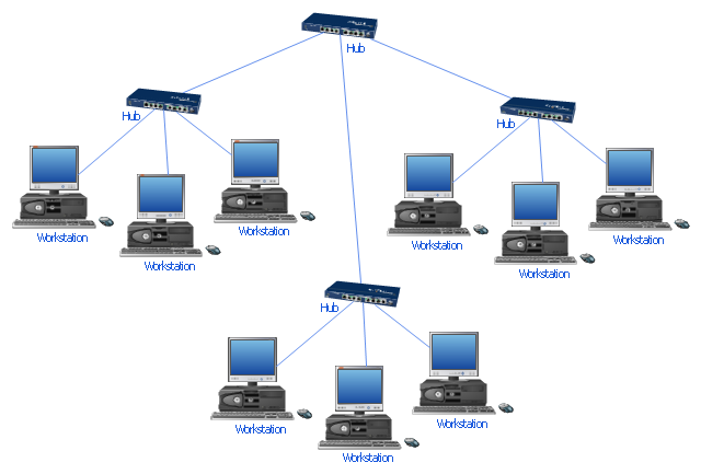
Hierarchical Network Topology

The vector stencils library "Logical symbols" contains 49 logical symbols for drawing logical network topology diagrams.
"Logical topology, or signal topology, is the arrangement of devices on a computer network and how they communicate with one another. How devices are connected to the network through the actual cables that transmit data, or the physical structure of the network, is called the physical topology. Physical topology defines how the systems are physically connected. It represents the physical layout of the devices on the network. The logical topology defines how the systems communicate across the physical topologies.
Logical topologies are bound to network protocols and describe how data is moved across the network. ... EXAMPLE : twisted pair Ethernet is a logical bus topology in a physical star topology layout. While IBM's token ring is a logical ring topology, it is physically set up in star topology." [Logical topology. Wikipedia]
The icons example "Logical symbols - Vector stencils library" was created using the ConceptDraw PRO diagramming and vector drawing software extended with the Computer and Networks solution from the Computer and Networks area of ConceptDraw Solution Park.
www.conceptdraw.com/ solution-park/ computer-and-networks
Coaxial Line Tag

Fiber Optic Line Tag

Twisted Pair Line Tag

SC2200 Signaling Controller

Bridge

Network Management Appliance

Access Server (Communications Server)
-logical-symbols---vector-stencils-library.png--diagram-flowchart-example.png)
Terminal Server

Web Browser

Security Management, Cisco

Lock and Key

Lock

Key

Relational Database

Host

CSU/DSU

WAN

University

Government building

Home Office

Telecommuter House PC

Medium Building, Regular

Headquarters, Subdued

House, Regular

Small Business

Network Connector

Dynamic Connector

Line Connector

Line-curve Connector

Bus

FDDI Ring

Peer-to-peer

Token-ring

Star

Comm-link

Curved Bus

Ethernet

Cloud

Speaker

Microphone

Router

ATM Router

ISDN Switch

ATM Switch

ATM/FastGB Etherswitch

Workgroup Switch

Small Hub

100BaseT Hub

CDDI-FDDI

"Logical topology, or signal topology, is the arrangement of devices on a computer network and how they communicate with one another. How devices are connected to the network through the actual cables that transmit data, or the physical structure of the network, is called the physical topology. Physical topology defines how the systems are physically connected. It represents the physical layout of the devices on the network. The logical topology defines how the systems communicate across the physical topologies.
Logical topologies are bound to network protocols and describe how data is moved across the network. ...
EXAMPLE : twisted pair Ethernet is a logical bus topology in a physical star topology layout. while IBM's token ring is a logical ring topology, it is physically set up in star topology." [Logical topology. Wikipedia]
This Cisco logical computer network diagram example was created using the ConceptDraw PRO diagramming and vector drawing software extended with the Cisco Network Diagrams solution from the Computer and Networks area of ConceptDraw Solution Park.
Logical network topology diagram

Diagram of a Basic Computer Network. Computer Network Diagram Example

 Computer and Networks Area
The solutions from Computer and Networks Area of ConceptDraw Solution Park collect samples, templates and vector stencils libraries for drawing computer and network diagrams, schemes and technical drawings.
Wireless Network Topology

"Star networks are one of the most common computer network topologies. In its simplest form, a star network consists of one central switch, hub or computer, which act as a conduit to transmit messages. This consists of a central node, to which all other nodes are connected; this central node provides a common connection point for all nodes through a hub. In star topology, every node (computer workstation or any other peripheral) is connected to a central node called a hub or switch. The switch is the server and the peripherals are the clients. Thus, the hub and leaf nodes, and the transmission lines between them, form a graph with the topology of a star." [Star network. Wikipedia]
The computer network diagram example "10Base-T star topology" was created using the ConceptDraw PRO diagramming and vector drawing software extended with the Computer and Networks solution from the Computer and Networks area of ConceptDraw Solution Park.
The computer network diagram example "10Base-T star topology" was created using the ConceptDraw PRO diagramming and vector drawing software extended with the Computer and Networks solution from the Computer and Networks area of ConceptDraw Solution Park.
Star topology
ERD Symbols and Meanings


Personal area (PAN) networks. Computer and Network Examples
 networks")
Cisco Switches and Hubs. Cisco icons, shapes, stencils and symbols

Network diagrams with ConceptDraw DIAGRAM

Hotel Network Topology Diagram


How to draw Metro Map style infographics? Moscow, New York, Los Angeles, London

How to draw Metro Map style infographics? (New York)
</i> *")
 Network Layout Floor Plans
Network Layout Floor Plans solution extends ConceptDraw DIAGRAM software functionality with powerful tools for quick and efficient documentation the network equipment and displaying its location on the professionally designed Network Layout Floor Plans. Never before creation of Network Layout Floor Plans, Network Communication Plans, Network Topologies Plans and Network Topology Maps was not so easy, convenient and fast as with predesigned templates, samples, examples and comprehensive set of vector design elements included to the Network Layout Floor Plans solution. All listed types of plans will be a good support for the future correct cabling and installation of network equipment.
- Ring Network Topology | Tree Network Topology Diagram | Hybrid ...
- Draw And Label A Star Topology
- Draw Ring Topology
- Draw And Label Topology On The Network
- Draw And Label The Diagram Of Star Topology
- A Well Labelled Diagram Of Ring Topology
- A Well Labeled Diagram Of A Ring Topology
- Www Mesh Topology With Its Component Label
- Draw A Diagram Of Ring Topology
- Logical network topology diagram | Diagram Of Ring Topology
- Draw And Label A Bus Topology
- Hybrid Network Topology | Tree Network Topology Diagram ...
- Draw And Label Star Network Topology Com
- Draw Structure Of Star Topology
- Star Topology 3d Drawing
- Draw Labeled Diagram For Tree Topology And Hybrid Topology
- Cafe and Restaurant Floor Plans | Draw And Label An Hybrid ...
- Draw And Label The Line Topology
- Network Drawing Software | Interactive Voice Response Network ...