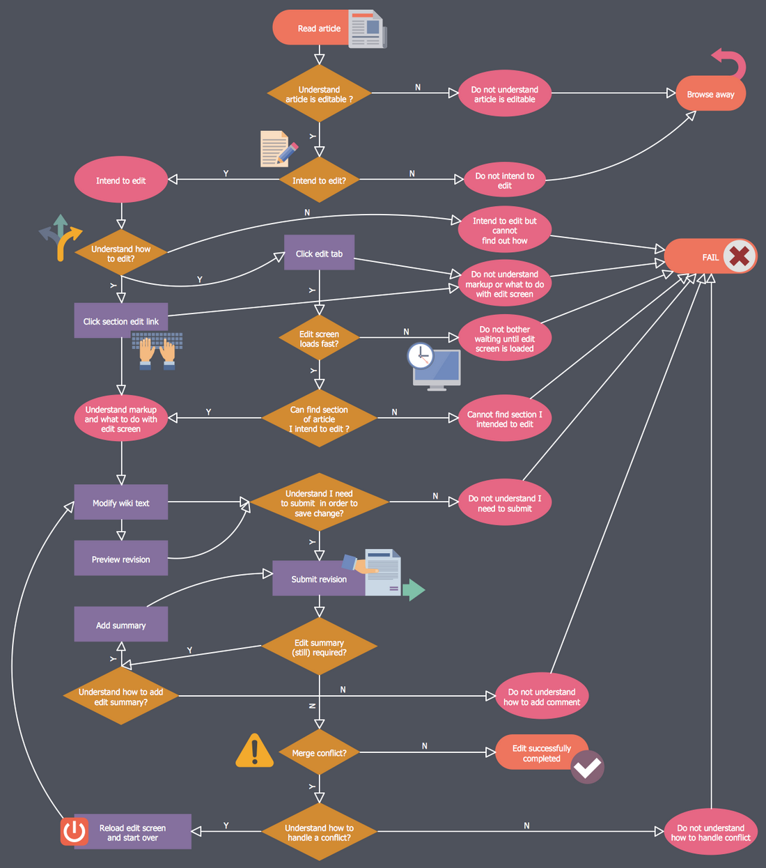
Business Process Workflow Diagram

HelpDesk
How to Add and Edit Connector Text

HelpDesk
How to Create an SDL Diagram

Swim Lane Diagrams

HelpDesk
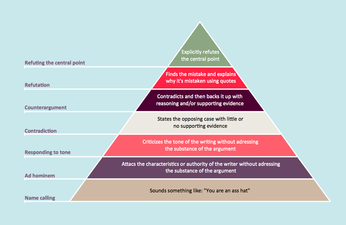
How to Draw a Pyramid Diagram
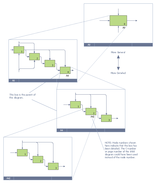
This IDEF0 diagram example was redesigned from the Wikimedia Commons file: 6 Decomposition Structure.svg.
[commons.wikimedia.org/ wiki/ File:6_ Decomposition_ Structure.svg]
"Functional decomposition refers broadly to the process of resolving a functional relationship into its constituent parts in such a way that the original function can be reconstructed (i.e., recomposed) from those parts by function composition. In general, this process of decomposition is undertaken either for the purpose of gaining insight into the identity of the constituent components (which may reflect individual physical processes of interest, for example), or for the purpose of obtaining a compressed representation of the global function, a task which is feasible only when the constituent processes possess a certain level of modularity (i.e., independence or non-interaction). Interactions between the components are critical to the function of the collection. All interactions may not be observable, but possibly deduced through repetitive perception, synthesis, validation and verification of composite behavior." [Functional decomposition. Wikipedia]
The example "IDEF0 diagram - Decomposition structure" was created using the ConceptDraw PRO diagramming and vector drawing software extended with the solution "IDEF Business Process Diagrams" from the area "Business Processes" of ConceptDraw Solution Park.
IDEF0 business process diagram
HelpDesk
How to Create an Enterprise Architecture Diagram

HelpDesk
How to Create a Venn Diagram

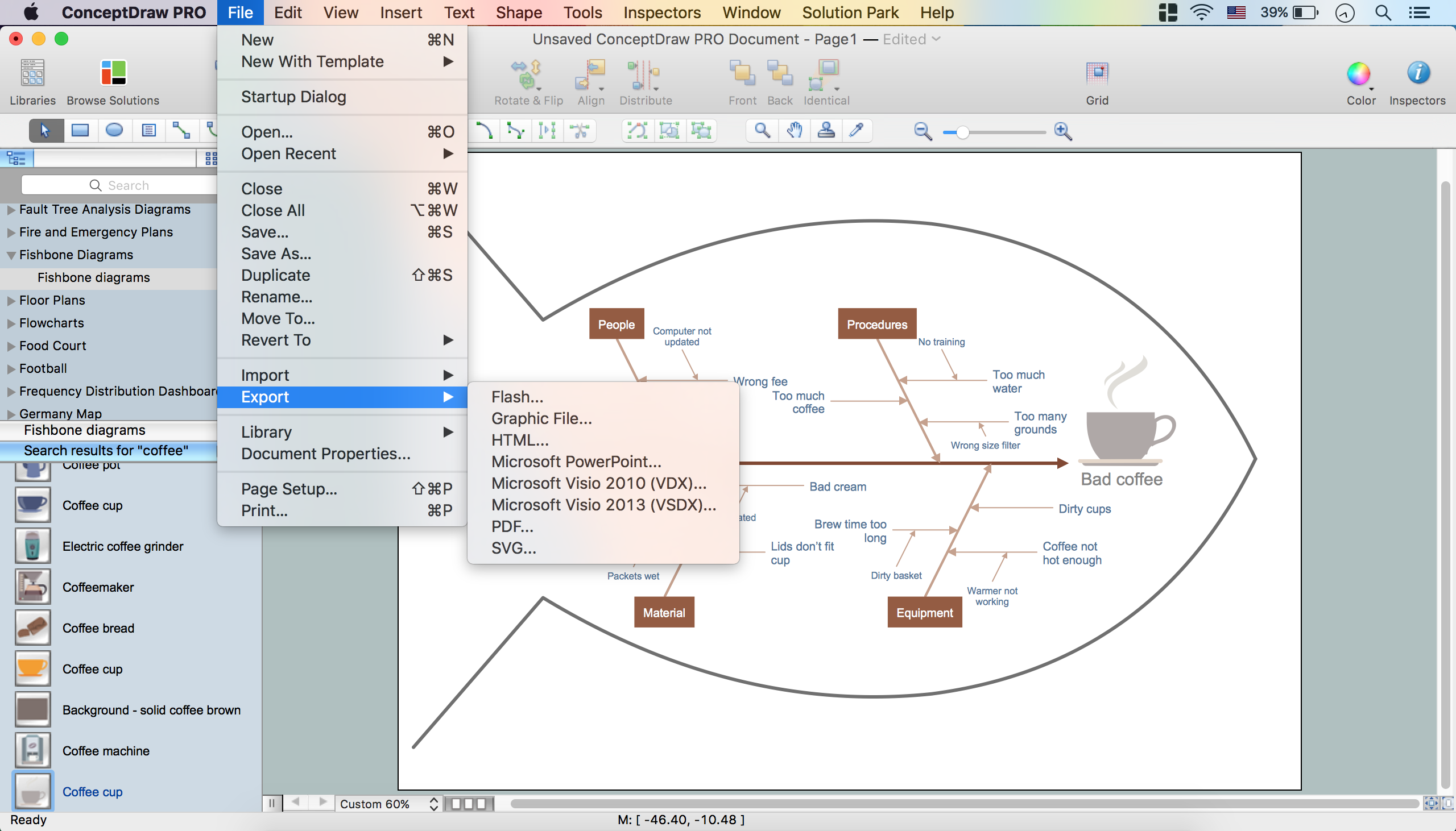
How to Construct a Fishbone Diagram
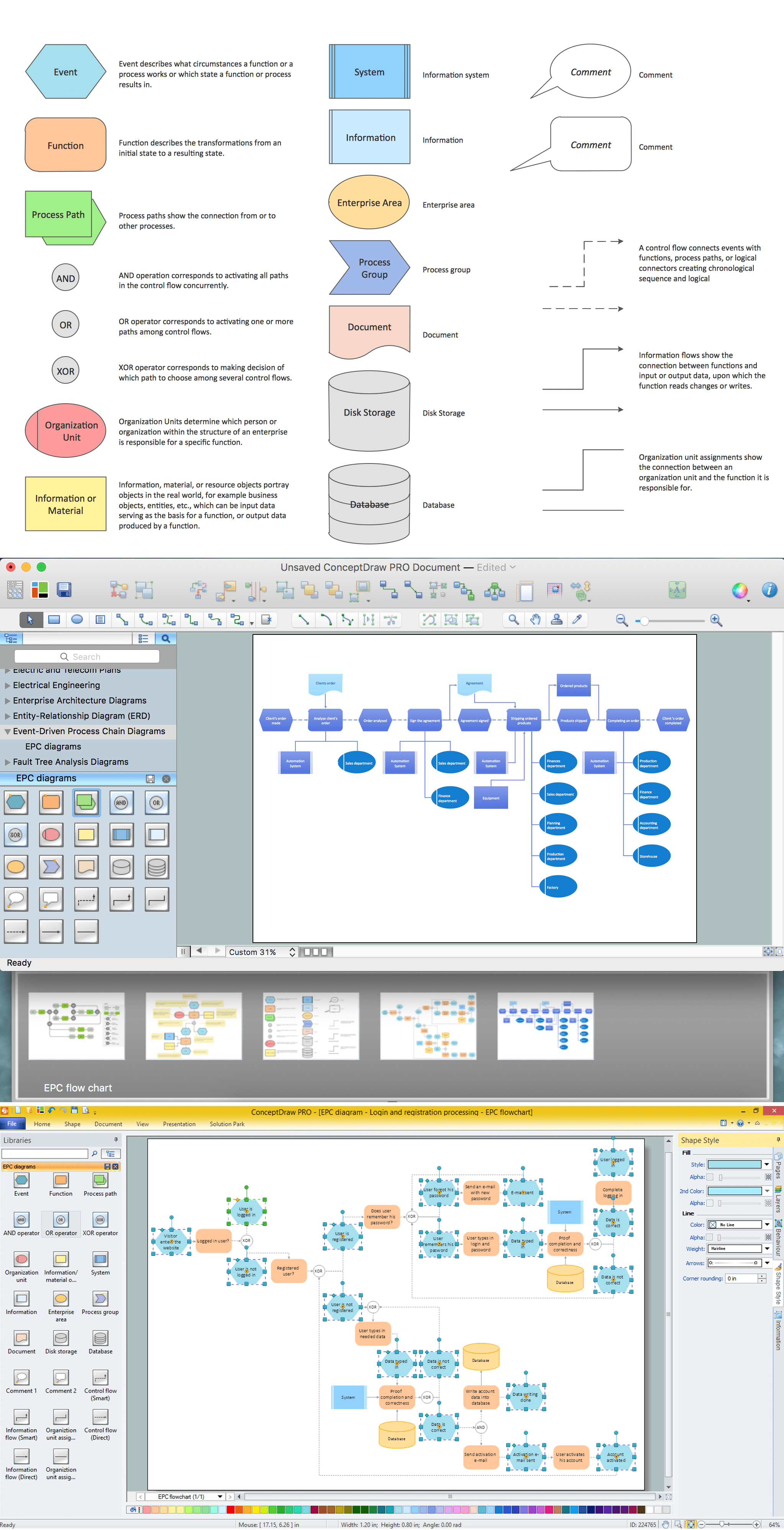
How to Draw EPC Diagram Quickly

HelpDesk
How to Draw a Circle-Spoke Diagram

 Business Process Diagrams
Business Process Diagrams solution extends the ConceptDraw DIAGRAM BPM software with RapidDraw interface, templates, samples and numerous libraries based on the BPMN 1.2 and BPMN 2.0 standards, which give you the possibility to visualize equally easy simple and complex processes, to design business models, to quickly develop and document in details any business processes on the stages of project’s planning and implementation.
HelpDesk
How to Create an IDEF3 Diagram

Business diagrams & Org Charts with ConceptDraw DIAGRAM

HelpDesk
How to Create a BPMN Diagram

- UML Use Case Diagram Example - Taxi Service | Business Process ...
- Draw Company Structure with Organization Charting Software ...
- How to Add Text to a Connector in ConceptDraw PRO | Swim Lane ...
- Electrical Diagram Software | Business Process Workflow Diagram ...
- Fishbone Diagram Problem Solving | Using Fishbone Diagrams for ...
- Use Case Text Based Example Of Banking System
- Diagram Bpmn Inclusive Gateway
- Design elements - Android system icons (editor) | Electrical Diagram ...
- IDEF0 diagram - Decomposition structure
- Sap Business Process Diagrams
- IDEF0 diagram - Inter-box connections | IDEF Business Process ...
- Professional Business Analysis with Process Workflow Diagrams ...
- Business process Flow Chart - Event-Driven Process chain (EPC ...
- Business Process Diagrams | Process Flowchart | Business Process ...
- Ice Hockey Diagram – Defensive Strategy – Neutral Zone Trap ...
- Program to Make Flow Chart | BPR Diagram . Business Process ...
- Swim Lane Diagrams | Swim Lane Flowchart Symbols | Cross ...
- Payroll process - Swim lane process mapping diagram | Cross ...
- Business Function Diagram
- Data Flow Diagram | How to Connect a Live Object to a Text Data ...