Products
Solutions
Samples
Contact Us
Buy
Helpdesk
✕
Sign In
Sign In
My ConceptDraw
Profile
Cart 
Activate
My Activated Licenses
Upgrade Information
Download Product
Open Support Ticket
Sign Out
This site uses cookies. By continuing to browse the ConceptDraw site you are agreeing to our Use of Site Cookies.
Helpdesk  >  ConceptDraw DIAGRAM  >    Business-specific Drawings

How to Create an SDL Diagram

Specification and Description Language (SDL) is a hierarchical diagramming language. SDL diagrams are used to visualize the architecture of real-time and event-driven systems involving many concurrent processes that communicate using discrete signals. ConceptDraw‘s Specification and Description Language solution contains a complete set of scalable and versatile objects to diagram the structure of any engineering system.
  1. Run ConceptDraw DIAGRAM.
  2. Find the Specification and Description Language (SDL) solution in the Solutions panel.
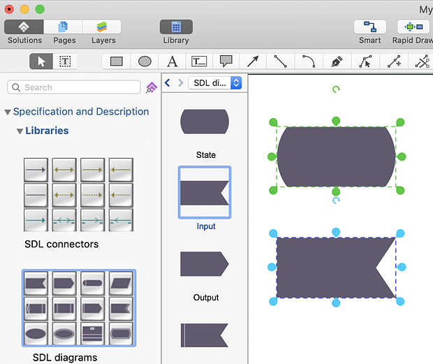
  3. Select the SDL library.
  4. To add a library object to your drawing, just click on an object and then click on the page, at the place you want the object to be inserted.
  5. sdl-diagram-elements
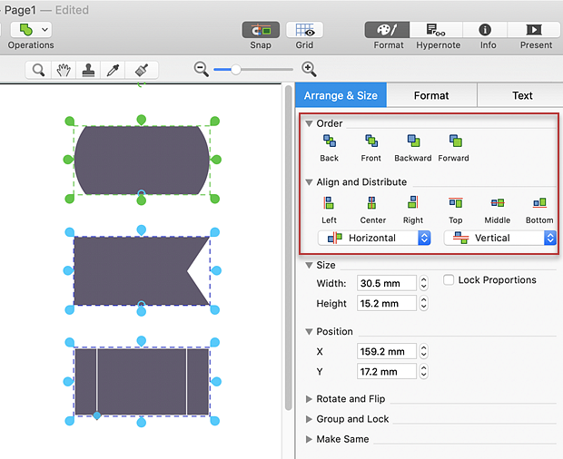
  6. Arrange objects properly using the options provided in the Arrange & Size panel.
  7. sdl-diagram-elements
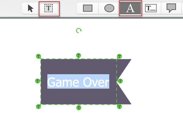
  8. To add text to an object just select an object and type. If you need to edit the existing text, click an object to activate the Text Tools.
  9. sdl-diagram
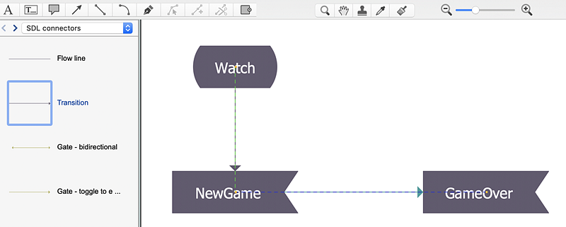
  10. Connect diagram objects using the Connectors library, which contains connectors defined by SDL specification. Drag the connector from one connect dot to another.
  11. conceptdraw-sdl

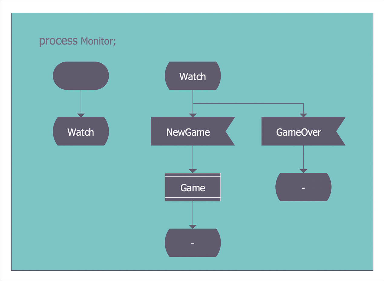
Result: SDL diagrams can be used to represent telecommunication systems, railway control systems, automotive systems, remote control systems, and various robotic systems.

Create an SDL Diagram

How it works:

  • Set of ready-to-use templates supplied with ConceptDraw DIAGRAM
  • Collection of professional samples supports each template
  • Professional drawing tools

Useful Solutions and Products:

Engineering area
  • Audio and Video Connectors
  • Chemical and Process Engineering
  • Electrical Engineering
  • Fault Tree Analysis Diagrams
  • Mechanical Engineering

Business Processes area
  • IDEF Business Process Diagrams
  • BPMN 2.0 Business Process Diagrams
  • Cross-Functional Flowcharts
  • Event-driven Process Chain Diagrams EPC
  • Workflow Diagrams

ConceptDraw DIAGRAM
  • Diagraming and Charts
  • Vector Illustrations
  • Maps
  • Floor plans
  • Engineering drawings
  • Business dashboards
  • Infographics
  • Presentation
  • Over 10 000 vector stencils
  • Export to vector graphics files
  • Export to Adobe Acrobat® PDF
  • Export to MS PowerPoint®
  • Export to MS Visio® VSDX, VDX

Products

  • ConceptDraw OFFICE v11
  • ConceptDraw DIAGRAM v18
  • ConceptDraw MINDMAP v16
  • ConceptDraw PROJECT v15
  • ConceptDraw STORE
  • ConceptDraw BOOKS

Solutions

  • Free
  • Premium

Samples

Support

  • Technical Support
  • Upgrade Request
  • Visio File Conversion
  • System Requirements
  • Helpdesk
  • Students & Educators
  • Enterprise
  • Customer Service

Solutions

  • Free
  • Premium

Samples

Video Room

  • Products
  • Solutions

Ready To Buy

  • Buy Online
  • Reseller Partners
  • Manage Your Account
  • Download Your Software
  • CS Odessa

    • About Us
    • Contact Us
    • CS Odessa Identity
    • News
  • CS Odessa
    Plan. Do. Communicate.

    About Us | Contact Us | Feedback | EULA | Privacy | TOU | TOS
    © 1993 — 2025 CS Odessa Corp.