UML Activity Diagram. Design Elements


Accounting Flowchart Symbols

UML Diagrams with ConceptDraw DIAGRAM

UML Diagrams with ConceptDraw DIAGRAM
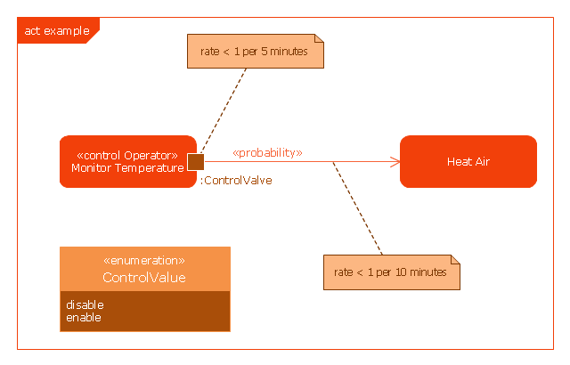
This example was drawn on the base of SysML activity diagram on the page 8 of "SysML Modelling Language explained" document from the Official OMG SysML site.
"The activity diagram represents steps of a process, often making use of “input and output pins” that respectively correspond to the element type required as the input of an activity or action, and the element generated as an output.
If an action or activity corresponds to a block operation, it is possible to ensure that the types of the input and output of this activity are consistent with the block operation signature.
All the activity diagrams definitions used in UML also apply to SysML.
SysML has added a couple of extensions:
- With UML, control can only enable actions to start. SysML extends control to support disabling of actions that are already executing.
- Definition of the flow rate : continuous or discrete
- Definition of the rate and probability on the control or object flows"
[omgsysml.org/ SysML_ Modelling_ Language_ explained-finance.pdf]
The example "SysML activity diagram" was drawn using the ConceptDraw PRO diagramming and vector drawing software extended with the SysML solution from the Software Development area of ConceptDraw Solution Park.
Example of SysML activity diagram
 ATM UML Diagrams
The ATM UML Diagrams solution lets you create ATM solutions and UML examples. Use ConceptDraw DIAGRAM as a UML diagram creator to visualize a banking system.
Diagramming Software for Design UML Component Diagrams

UML Use Case Diagram Example - Estate Agency

Purchase Process Flow Chart, Receiving Process Flow Chart, Accounting Flowchart Example.

Flowchart Programming Project. Flowchart Examples

 Rapid UML
Rapid UML solution extends ConceptDraw DIAGRAM software with templates, samples and libraries of vector stencils for quick drawing the UML diagrams using Rapid Draw technology.
UML Diagram Tool

UML Deployment Diagram. Design Elements

Developing Entity Relationship Diagrams

Basic Flowchart Symbols and Meaning


Business process Flow Chart — Event-Driven Process chain (EPC) diagrams
 diagrams *")
HelpDesk
How to Create a Bank ATM Use Case Diagram

 Flowcharts
The Flowcharts solution for ConceptDraw DIAGRAM is a comprehensive set of examples and samples in several varied color themes for professionals that need to represent graphically a process. Solution value is added by the basic flow chart template and shapes' libraries of flowchart notation. ConceptDraw DIAGRAM flow chart creator lets one depict the processes of any complexity and length, as well as design the Flowchart either vertically or horizontally.
 SYSML
SYSML
The SysML solution helps to present diagrams using Systems Modeling Language; a perfect tool for system engineering.
Diagramming Software for UML Composite Structure Diagrams

- UML activity diagram - User registration | UML Use Case Diagram ...
- Cross Functional Flowchart Shapes | Vertical Cross Functional ...
- Electrical Symbols — Terminals and Connectors | How to Add and ...
- Draw The Flowchart Symbol For Input Output Decision Off Page
- Activities BPMN 1.2 - Vector stencils library | Design elements ...
- Flowchart Symbols Off Page Connector
- UML activity diagram - User registration
- On Page Connector
- UML Block Diagram
- Basic Flowchart Symbols and Meaning | Business Process ...
- Off Page Connector Meaning
- Flowchart - Vector stencils library | Design elements - Accounting ...
- Events - Vector stencils library
- Data Flow Diagram | BPMN 2.0 | Sales Flowcharts | Activity Diagram ...
- UML Diagram | UML Class Diagram . Design Elements | Venn ...
- UML Class Diagram Example for GoodsTransportation System ...
- Design elements - Events BPMN 2.0 | Design elements - Data ...
- Design elements - Activities BPMN 2.0 | Design elements - Events ...
- http://www.conceptdraw.com/examples/uuo-element daily 0.56 http ...