Personal area (PAN) networks. Computer and Network Examples
 networks")

Metropolitan area networks (MAN). Computer and Network Examples
. Computer and Network Examples")
Local area network (LAN). Computer and Network Examples
 diagram")
Diagram of a Basic Computer Network. Computer Network Diagram Example

Business Process Flow Diagram

Hypercube Network Topology

 Network Layout Floor Plans
Network Layout Floor Plans solution extends ConceptDraw DIAGRAM software functionality with powerful tools for quick and efficient documentation the network equipment and displaying its location on the professionally designed Network Layout Floor Plans. Never before creation of Network Layout Floor Plans, Network Communication Plans, Network Topologies Plans and Network Topology Maps was not so easy, convenient and fast as with predesigned templates, samples, examples and comprehensive set of vector design elements included to the Network Layout Floor Plans solution. All listed types of plans will be a good support for the future correct cabling and installation of network equipment.
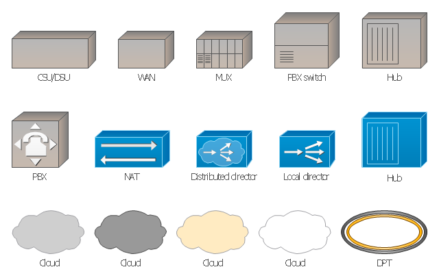
The vector stencils library "Cisco WAN" contains 15 symbols of wide area network (WAN) devices and equipment: CSU/ DSU (Channel Service Unit/ Data Service Unit), WAN, MUX (multiplexer), PBX switch, Hub, NAT (network address translation), distributed and local directors, PBX (private branch exchange), Network clouds, DPT (dynamic packet transport).
Create the computer network topology diagrams using the ConceptDraw PRO diagramming and vector drawing software with the design elements library "Cisco WAN".
"A wide area network (WAN) is a network that covers a broad area (i.e., any telecommunications network that links across metropolitan, regional, or national boundaries) using private or public network transports. Business and government entities utilize WANs to relay data among employees, clients, buyers, and suppliers from various geographical locations. In essence, this mode of telecommunication allows a business to effectively carry out its daily function regardless of location. The Internet can be considered a WAN as well, and is used by businesses, governments, organizations, and individuals for almost any purpose imaginable.
Related terms for other types of networks are personal area networks (PANs), local area networks (LANs), campus area networks (CANs), or metropolitan area networks (MANs) which are usually limited to a room, building, campus or specific metropolitan area (e.g., a city) respectively." [Wide area network. Wikipedia]
The example "Design elements - Cisco WAN" is included in the Cisco Network Diagrams solution from the Computer and Networks area of ConceptDraw Solution Park.
Cisco WAN symbols
Electrical Symbols, Electrical Diagram Symbols

Star Network Topology


Block Diagram

Cisco Wireless Network Diagram

Fully Connected Network Topology Diagram

Hybrid Network Topology

Network Topologies

How to Dramatically Reduce Drawing Time - New connection modes

Network Topology

"A computer network or data network is a telecommunications network that allows computers to exchange data. In computer networks, networked computing devices (network nodes) pass data to each other along data connections. The connections (network links) between nodes are established using either cable media or wireless media. The best-known computer network is the Internet.
Network devices that originate, route and terminate the data are called network nodes. Nodes can include hosts such as servers and personal computers, as well as networking hardware. Two devices are said to be networked when a device is able to exchange information with another device." [Computer network. Wikipedia]
This computer communication network diagram example was created using the ConceptDraw PRO diagramming and vector drawing software extended with the Computer and Networks solution from the Computer and Networks area of ConceptDraw Solution Park.
Network diagram

- A Well Labelled Diargram Of A Headpan
- Well Label Diagram Of Head Pan
- | Diagram Of A Well Labelled Headpan
- Diagram Of A Well Labeled Head Pan
- Labelled Diagram Of A Head Pan
- Local area network (LAN). Computer and Network Examples ...
- Local area network (LAN). Computer and Network Examples ...
- With Aid Of A Diagram Draw Head Pan
- | How To Draw Headpan
- Business Process Mapping | Www Draw And Label A Head Pan
- Fully Connected Network Topology Diagram | Fishbone Diagram ...
- What Is Headpan Used For
- Draw A Headpan
- Basic Network Diagram | What Is The Use Of Head Pan
- Sketch Of Headpan
- | How To Label A Headpan
- Network Diagram Software Logical Network Diagram | Fishbone ...
- Personal area ( PAN ) networks. Computer and Network Examples ...
- Personal area ( PAN ) networks. Computer and Network Examples ...