UML Class Diagram Example - Medical Shop

This sample shows the work of the medical shop and is used at the creation of the medical shop or pharmacy project, for understanding the process of shopping in the medical shop, for keeping purchases, for medical supplies.
UML Class Diagram. Design Elements

Class Diagram Tool
DFD Flowchart Symbols

IDEF1X Standard

Entity Relationship Diagram - ERD - Software for Design Crows Foot ER Diagrams
_Win_Mac.png)

Telecommunications Networks

UML Collaboration Diagram (UML2.0)

Rapid UML solution provides templates, examples and libraries of stencils for quick and easy drawing all the types of system and software engineering diagrams according to UML 2.4 and 1.2 notations.

IDEF3 Standard

Example of DFD for Online Store (Data Flow Diagram)

Example of DFD for Online Store shows the Data Flow Diagram for online store and interactions between the Visitors, Customers and Sellers, as well as Website Information and User databases.

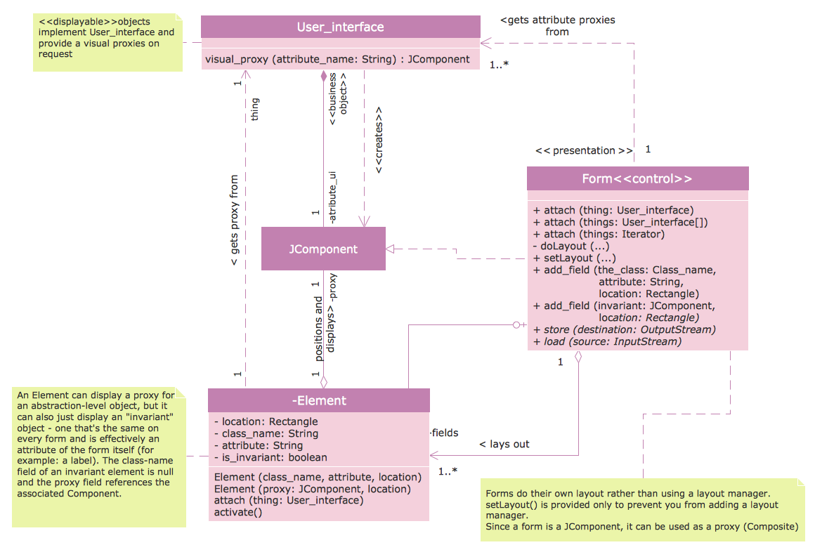
UML Notation

Two types of diagrams are used in UML: Structure Diagrams and Behavior Diagrams. Behavior Diagrams represent the processes proceeding in a modeled environment. Structure Diagrams represent the elements that compose the system.
Product Overview
Entity-Relationship Diagram (ERD) with ConceptDraw DIAGRAM

one-to-many, many-to-many.
Draw Entity-Relationship Diagrams (ERD) easily with ConceptDraw extended with Entity-Relationship Diagram (ERD) Solution from the Software Development Area. Use ERD software to create ER diagram.
- Activity Diagram Of Medical Shop System
- UML Class Diagram Example - Medical Shop | UML Notation | UML ...
- UML Class Diagram Example - Medical Shop | How to create a UML ...
- UML Class Diagram Example - Medical Shop | UML Diagram for ...
- Uml Diagrams For Medical Store Management System
- UML Class Diagram Example - Medical Shop | Online Diagram Tool ...
- UML Class Diagram Example - Medical Shop | UML Tool & UML ...
- Medical Shop Management System Uml Diagrams
- Uml Diagram Of Medical Shop Management System
- UML Class Diagram Example - Medical Shop
- UML Class Diagram Example - Medical Shop | State Diagram ...
- UML Class Diagram Example - Medical Shop | Process Flowchart ...
- UML Class Diagram Example - Medical Shop
- UML Class Diagram Example - Medical Shop
- UML Class Diagram Example - Medical Shop | UML Component ...
- UML Class Diagram Example - Medical Shop | UML Class Diagram ...
- UML Class Diagram Example - Medical Shop | UML Collaboration ...
- UML Class Diagram Example - Medical Shop
- Medical Store Management System Use Case Diagram
- UML Class Diagram Example - Medical Shop | UML Diagram ...
- ERD | Entity Relationship Diagrams, ERD Software for Mac and Win
- Flowchart | Basic Flowchart Symbols and Meaning
- Flowchart | Flowchart Design - Symbols, Shapes, Stencils and Icons
- Flowchart | Flow Chart Symbols
- Electrical | Electrical Drawing - Wiring and Circuits Schematics
- Flowchart | Common Flowchart Symbols
- Flowchart | Common Flowchart Symbols