HelpDesk
How to Create a CCTV Diagram in ConceptDraw PRO

CCTV diagram should include the scheme of strategic placement of video cameras, which capture and transmit videos to either a private network of monitors for real-time viewing, or to a video recorder for later reference. CCTV is commonly used for surveillance and security purposes. Using ConceptDraw PRO with the Security and Access Plans Solution lets you create professional looking video surveillance CCTV system plans, security plans, and access schemes.
HelpDesk
Event-driven Process Chain (EPC) Diagram Software

An EPC diagram shows different business processes through various workflows. The workflows are seen as functions and events that are connected by different teams or people, as well as tasks that allow business processes to be executed. The best thing about this type of enterprise modelling is that creating an EPC diagram is quick and simple as long as you have the proper tool. One of the main usages of the EPC diagrams is in the modelling, analyzing and re-engineering of business processes. With the use of the flowchart, businesses are able to see inefficiencies in the processes and modify to make them more productive. Event-driven process chain diagrams are also used to configure an enterprise resource pla
This AV connector pinout diagram example was redesigned from the file: DVI pinout.svg. [en.wikipedia.org/ wiki/ File:DVI_ pinout.svg]
"In electronics, a pinout (sometimes written "pin-out") is a cross-reference between the contacts, or pins, of an electrical connector or electronic component, and their functions. ...
The functions of contacts in electrical connectors, be they power- or signaling-related, must be specified in order for connectors to be interchangeable. When connected, each contact of a connector must mate with the contact on the other connector that has the same function. If contacts of disparate functions are allowed to make contact, the connection may fail and damage may result. Therefore, pinouts are a vital reference when building and testing connectors, cables, and adapters." [Pinout. Wikipedia]
The example "DVI pinout diagram" was created using the ConceptDraw PRO diagramming and vector drawing software extended with the Audio and Video Connectors solution from the Engineering area of ConceptDraw Solution Park.
A female DVI-I socket from the front

 IDEF Business Process Diagrams
Use the IDEF Business Process Diagrams solution to create effective database designs and object-oriented designs, following the integration definition methodology.
 ConceptDraw Solution Park
ConceptDraw Solution Park collects graphic extensions, examples and learning materials
The vector stencils library "IDEF0 diagrams" contains 18 symbols for drawing IDEF0 function modeling diagrams using the ConceptDraw PRO diagramming and vector drawing software.
"The IDEF0 model ... is based on a simple syntax. Each activity is described by a verb-based label placed in a box. Inputs are shown as arrows entering the left side of the activity box while output are shown as exiting arrows on the right side of the box. Controls are displayed as arrows entering the top of the box and mechanisms are displayed as arrows entering from the bottom of the box. Inputs, Controls, Outputs, and Mechanisms are all referred to as concepts.
- Arrow : A directed line, composed of one or more arrow segments, that models an open channel or conduit conveying data or objects from source (no arrowhead) to use (with arrowhead). There are 4 arrow classes: Input Arrow, Output Arrow, Control Arrow, and Mechanism Arrow (includes Call Arrow). See Arrow Segment, Boundary Arrow, Internal Arrow.
- Box : A rectangle, containing a name and number, used to represent a function.
- Context : The immediate environment in which a function (or set of functions on a diagram) operates.
- Decomposition : The partitioning of a modeled function into its component functions.
- Fork : The junction at which an IDEF0 arrow segment (going from source to use) divides into two or more arrow segments. May denote unbundling of meaning.
- Function : An activity, process, or transformation (modeled by an IDEF0 box) identified by a verb or verb phrase that describes what must be accomplished.
- Join : The junction at which an IDEF0 arrow segment (going from source to use) merges with one or more other arrow segments to form a single arrow segment. May denote bundling of arrow segment meanings.
- Node : A box from which child boxes originate; a parent box. See Node Index, Node Tree, Node Number, Node Reference, Diagram Node Number." [IDEF0. Wikipedia]
The example "Design elements - IDEF0 diagram" is included in the IDEF0 Diagrams solution from the Software Development area of ConceptDraw Solution Park.
IDEF0 symbols

 Mathematics
Mathematics solution extends ConceptDraw PRO software with templates, samples and libraries of vector stencils for drawing the mathematical illustrations, diagrams and charts.
 IDEF0 Diagrams
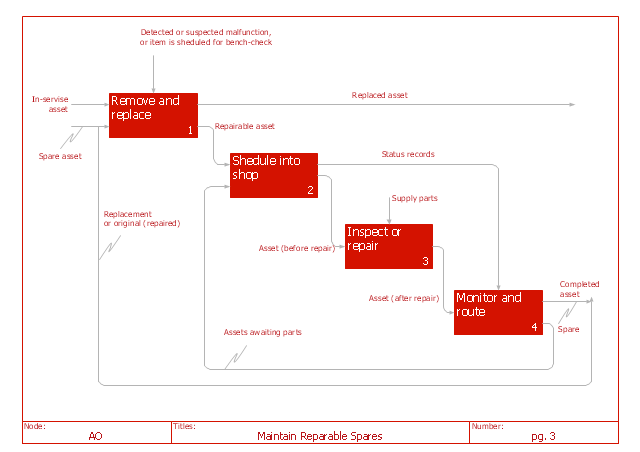
IDEF0 Diagrams visualize system models using the Integration Definition for Function Modeling (IDEF) methodology. Use them for analysis, development and integration of information and software systems, and business process modelling.
"IDEF0 may be used to model a wide variety of automated and non-automated systems. For new systems, it may be used first to define the requirements and specify the functions, and then to design an implementation that meets the requirements and performs the functions. For existing systems, IDEF0 can be used to analyze the functions the system performs and to record the mechanisms (means) by which these are done. The result of applying IDEF0 to a system is a model that consists of a hierarchical series of diagrams, text, and glossary cross-referenced to each other. The two primary modeling components are functions (represented on a diagram by boxes) and the data and objects that inter-relate those functions (represented by arrows)." [IDEF0. Wikipedia]
The IDEF0 diagram example "Maintain reparable spares" was created using the ConceptDraw PRO diagramming and vector drawing software extended with the IDEF0 Diagrams solution from the Software Development area of ConceptDraw Solution Park.
The IDEF0 diagram example "Maintain reparable spares" was created using the ConceptDraw PRO diagramming and vector drawing software extended with the IDEF0 Diagrams solution from the Software Development area of ConceptDraw Solution Park.
IDEF0 diagram
- Circuits and Logic Diagram Software | Electrical Drawing Software ...
- Engineering | Electrical Diagram Software | Design elements ...
- Engineering | Electrical Diagram Software | Wiring Diagram Floor ...
- Logic gate diagram - Template
- Amplifier - Circuit diagram | Design elements - Composite ...
- Electrical Diagram Software | Wiring Diagram Floor Software ...
- Logic Gate Circuit Diagram Maker
- Electrical Drawing Software | How To use House Electrical Plan ...
- Block Diagrams | Create Block Diagram | Basic Diagramming | Block ...
- Block Diagrams | Create Block Diagram | Types of Flowcharts ...
- Electrical Drawing Software | Design elements - Electrical circuits ...
- Engineering | Design elements - Analog and digital logic | Electrical ...
- Electrical Engineering | How to Create an Electrical Diagram ...
- 5 level pyramid model diagram of information systems types ...
- Circuits and Logic Diagram Software | Design elements - Logic gate ...
- Draw Block Diagram Communication System Osx
- Design elements - Composite assemblies | Design elements ...
- Electrical Diagram Software | How To use House Electrical Plan ...
- How To use Electrical and Telecom Plan Software | Design elements
- IDEF0 diagram template | Business Processes | Cross-Functional ...
- ERD | Entity Relationship Diagrams, ERD Software for Mac and Win
- Flowchart | Basic Flowchart Symbols and Meaning
- Flowchart | Flowchart Design - Symbols, Shapes, Stencils and Icons
- Flowchart | Flow Chart Symbols
- Electrical | Electrical Drawing - Wiring and Circuits Schematics
- Flowchart | Common Flowchart Symbols
- Flowchart | Common Flowchart Symbols