Electrical Symbols, Electrical Diagram Symbols

This solution provides 26 libraries which contain 926 electrical symbols from electrical engineering: Analog and Digital Logic, Composite Assemblies, Delay Elements, Electrical Circuits, Electron Tubes, IGFET, Inductors, Integrated Circuit, Lamps, Acoustics, Readouts, Logic Gate Diagram, MOSFET, Maintenance, Power Sources, Qualifying, Resistors, Rotating Equipment, Semiconductor Diodes, Semiconductors, Stations, Switches and Relays, Terminals and Connectors, Thermo, Transformers and Windings, Transistors, Transmission Paths,VHF UHF SHF.
Electrical Symbols — Delay Elements

26 libraries of the Electrical Engineering Solution of ConceptDraw DIAGRAM make your electrical diagramming simple, efficient, and effective. You can simply and quickly drop the ready-to-use objects from libraries into your document to create the electrical diagram.
Electrical Symbols — Thermo

26 libraries of the Electrical Engineering Solution of ConceptDraw DIAGRAM make your electrical diagramming simple, efficient, and effective. You can simply and quickly drop the ready-to-use objects from libraries into your document to create the electrical diagram.
Electrical Drawing Software and Electrical Symbols

Electrical Drawing Software provides the 26 stencils libraries of ready-to-use predesigned vector electrical symbols, templates and samples that make your electrical drawing quick, easy and effective.
The vector stencils library "Electrical circuits" contains 49 element symbols of electrical and electronic devices, including ignitors, starters, transmitters, circuit protectors, transducers, radio and audio equipment.
Use it for drawing electronic circuit diagrams and electrical schematics.
"An electrical network is an interconnection of electrical elements such as resistors, inductors, capacitors, voltage sources, current sources and switches. An electrical circuit is a network consisting of a closed loop, giving a return path for the current. Linear electrical networks, a special type consisting only of sources (voltage or current), linear lumped elements (resistors, capacitors, inductors), and linear distributed elements (transmission lines), have the property that signals are linearly superimposable. They are thus more easily analyzed, using powerful frequency domain methods such as Laplace transforms, to determine DC response, AC response, and transient response.
A resistive circuit is a circuit containing only resistors and ideal current and voltage sources. Analysis of resistive circuits is less complicated than analysis of circuits containing capacitors and inductors. If the sources are constant (DC) sources, the result is a DC circuit.
A network that contains active electronic components is known as an electronic circuit. Such networks are generally nonlinear and require more complex design and analysis tools." [Electrical network. Wikipedia]
The symbils example "Design elements - Electrical circuits" was drawn using the ConceptDraw PRO diagramming and vector drawing software extended with the Electrical Engineering solution from the Engineering area of ConceptDraw Solution Park.
Electrical circuit elements

Interior Design. Registers, Drills and Diffusers — Design Elements

Network Diagramming Software for Design Network Layout Diagrams
_Win_Mac.png "Network Diagramming Software for Design <br>Network Layout Diagrams *")

Interior Design. Machines and Equipment — Design Elements

Electrical Symbols — Resistors

26 libraries of the Electrical Engineering Solution of ConceptDraw DIAGRAM make your electrical diagramming simple, efficient, and effective. You can simply and quickly drop the ready-to-use objects from libraries into your document to create the electrical diagram.
The vector stencils library "Resistors" contains 14 element symbols of resistors for drawing electronic schematics, circuit diagrams and electrical drawings.
"A resistor is a passive two-terminal electrical component that implements electrical resistance as a circuit element. Resistors act to reduce current flow, and, at the same time, act to lower voltage levels within circuits. Resistors may have fixed resistances or variable resistances, such as those found in thermistors, varistors, trimmers, photoresistors and potentiometers.
The current through a resistor is in direct proportion to the voltage across the resistor's terminals. This relationship is represented by Ohm's law ...
Resistors are common elements of electrical networks and electronic circuits and are ubiquitous in electronic equipment. Practical resistors can be composed of various compounds and films, as well as resistance wires (wire made of a high-resistivity alloy, such as nickel-chrome). Resistors are also implemented within integrated circuits, particularly analog devices, and can also be integrated into hybrid and printed circuits." [Resistor. Wikipedia]
The shapes example "Design elements - Resistors" was drawn using the ConceptDraw PRO diagramming and vector drawing software extended with the Electrical Engineering solution from the Engineering area of ConceptDraw Solution Park.
Resistor symbols

The vector stencils library "Lamps, acoustics, readouts" contains 35 element symbols of lamps, acoustic components, electrical measuring instruments for drawing electrical schematics and electronic circuit diagrams.
"Electrical measurements are the methods, devices and calculations used to measure electrical quantities. Measurement of electrical quantities may be done to measure electrical parameters of a system. Using transducers, physical properties such as temperature, pressure, flow, force, and many others can be converted into electrical signals, which can then be conveniently measured and recorded." [Electrical measurements. Wikipedia]
"A lamp is a replaceable component such as an incandescent light bulb, which is designed to produce light from electricity." [Lamp (electrical component). Wikipedia]
"An electric bell is a mechanical bell that... functions by means of an electromagnet. When an electric current is applied, it produces a repetitive buzzing or clanging sound." [Electric bell. Wikipedia]
"A buzzer or beeper is an audio signalling device, which may be mechanical, electromechanical, or piezoelectric." [Buzzer. Wikipedia]
"Electronic sirens incorporate circuits such as oscillators, modulators, and amplifiers to synthesize a selected siren tone (wail, yelp, pierce/ priority/ phaser, hi-lo, scan, airhorn, manual, and a few more) which is played through external speakers." [Siren (noisemaker). Wikipedia]
"A microphone (colloquially called a mic or mike...) is an acoustic-to-electric transducer or sensor that converts sound in air into an electrical signal. ...
Most microphones today use electromagnetic induction (dynamic microphone), capacitance change (condenser microphone) or piezoelectric generation to produce an electrical signal from air pressure variations." [Microphone. Wikipedia]
The symbols example "Design elements - Lamps, acoustics, readouts" was drawn using the ConceptDraw PRO diagramming and vector drawing software extended with the Electrical Engineering solution from the Engineering area of ConceptDraw Solution Park.
Lamps, acoustics, electrical measuring instruments

Building Drawing Software for Design Piping Plan


Interior Design. Storage and Distribution — Design Elements

Aerospace - Design Elements

The vector stencils library "Delay elements" contains 12 symbols of delay elements for drawing electrical schematics and electronic circuit diagrams.
"An analog delay line is a network of electrical components connected in series, where each individual element creates a time difference or phase change between its input signal and its output signal. It operates on analog signals whose amplitude varies continuously. An example is a bucket-brigade device. Other types of delay line include acoustic, magnetostrictive, and surface acoustic wave devices. A series of RC networks can be cascaded to form a delay. A long transmission line can also provide a delay element. The delay time of an analog delay line may be only a few nanoseconds or several milliseconds, limited by the practical size of the physical medium used to delay the signal and the propagation speed of impulses in the medium." [Analog delay line. Wikipedia]
The symbols example "Design elements - Delay elements" was drawn using the ConceptDraw PRO diagramming and vector drawing software extended with the Electrical Engineering solution from the Engineering area of ConceptDraw Solution Park.
Delay element symbols

 Electrical Engineering
This solution extends ConceptDraw DIAGRAM.9.5 (or later) with electrical engineering samples, electrical schematic symbols, electrical diagram symbols, templates and libraries of design elements, to help you design electrical schematics, digital and analog
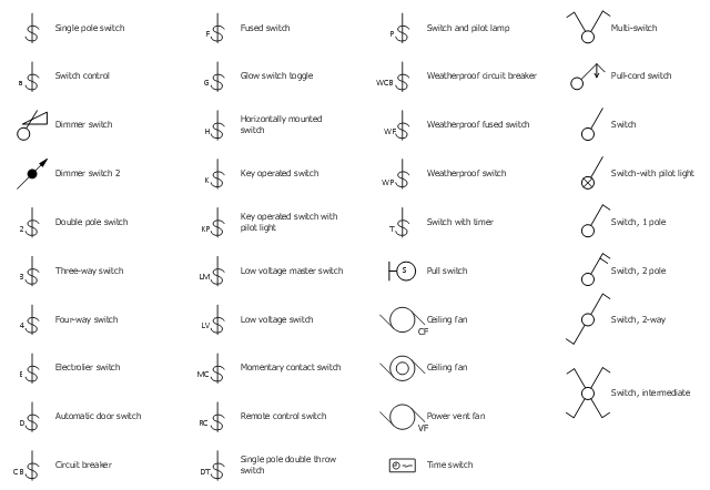
The vector stencil library "RCP-Electrical switches" contains 35 light switch symbols.
Use it to design your reflected ceiling plan with ConceptDraw DIAGRAM software.
"In electrical engineering, a switch is an electrical component that can "make" or "break" an electrical circuit, interrupting the current or diverting it from one conductor to another. The mechanism of a switch removes or restores the conducting path in a circuit when it is operated. It may be operated manually, for example, a light switch or a keyboard button, may be operated by a moving object such as a door, or may be operated by some sensing element for pressure, temperature or flow. A switch will have one or more sets of contacts, which may operate simultaneously, sequentially, or alternately." [Switch. Wikipedia]
"In electrical wiring, a light switch is a switch most commonly used to operate electric lights, permanently connected equipment, or electrical outlets. Portable lamps such as table lamps may have a light switch mounted on the socket, base, or in-line with the cord. Manually operated on/ off switches may be substituted by dimmer switches that allow controlling the brightness of lamps as well as turning them on or off, time-controlled switches, occupancy-sensing switches, and remotely controlled switches and dimmers." [Light switch. Wikipedia]
The light switch symbols example "Design Elements - RCP-Electrical switches" is included in Reflected Ceiling Plans solution from the Building Plans area of ConceptDraw Solution Park.
Vector stencils
Design Element: Computer and Network for Network Diagrams
.png "Design Element: Computer and Network<br>for Network Diagrams *")
ConceptDraw has 1004 vector stencils in the 40 libraries that helps you to start using software for designing own Network Diagrams. You can use the appropriate stencils from Computer and Network Diagrams library with 56 objects.
Aircraft - Design Elements

- Electrical Element
- Design elements - Thermo | Design elements - Electrical and ...
- Design elements - Electrical circuits | Design elements - Delay ...
- Phase Diagram Of Electrical Element
- Design elements - Appliances | Electrical Symbol For Cooker
- Design elements - Electrical circuits
- Electrical Symbols, Electrical Diagram Symbols | Design elements ...
- Design elements - Electrical and telecom | Design elements - Outlets ...
- Design elements - Electrical circuits | Design elements - Resistors ...
- Design elements - Delay elements | Symbols Of Electrical Impulse
- Design elements - Delay elements | Line Symbol Of Electrical Impulse
- Interior Design. Site Plan — Design Elements | How To use House ...
- Electrical Symbols — Thermo | Electrical Symbols — Resistors ...
- Design elements - Logic gate diagram | Electrical Drafting And ...
- Technical Drawing Software | Building Drawing. Design Element ...
- Design elements - Transformers and windings | Transformers and ...
- Telecommunication Network Diagrams | Design elements ...
- Design elements - Power sources | Electrical Engineering ...
- Seating Plans | Electric and Telecom Plans | Design elements ...
- How To use House Electrical Plan Software | Electrical Symbols ...
- ERD | Entity Relationship Diagrams, ERD Software for Mac and Win
- Flowchart | Basic Flowchart Symbols and Meaning
- Flowchart | Flowchart Design - Symbols, Shapes, Stencils and Icons
- Flowchart | Flow Chart Symbols
- Electrical | Electrical Drawing - Wiring and Circuits Schematics
- Flowchart | Common Flowchart Symbols
- Flowchart | Common Flowchart Symbols