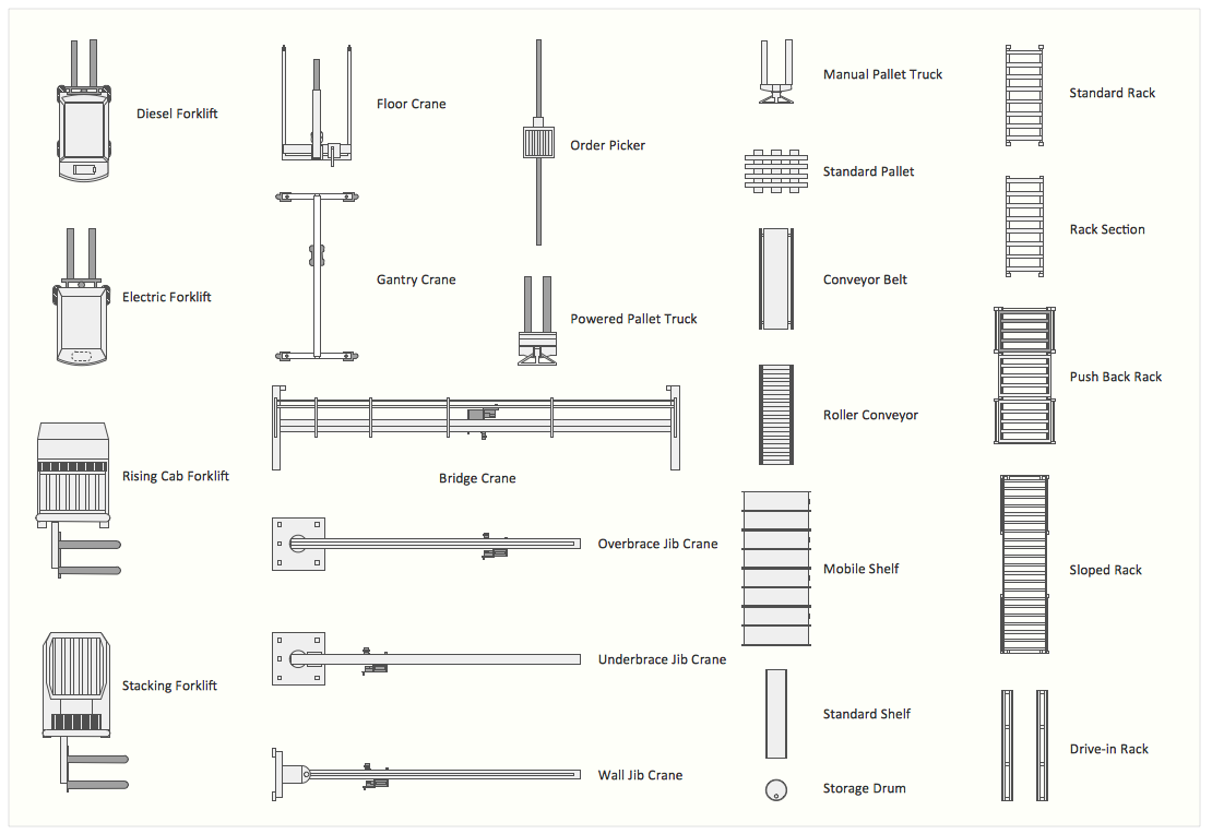
Sample 1. Design elements of storage and distribution plant layout plans for building drawing.
Solution Building Plans from ConceptDraw Solution Park provides vector stencils libraries with design elements for drawing plant layout plans.
Use ConceptDraw DIAGRAM diagramming and vector drawing software enhanced with Building Plans solution to draw your own plant layouts for production, storage, distribution, transport, shipping and receiving of manufactured goods.
Read more about Home and Landscape design
NINE RELATED HOW TO's:
Chemistry solution offers 6 libraries with large collection of vector chemistry symbols and meanings, chemistry equation symbols, organic chemistry symbols, and chemical clipart.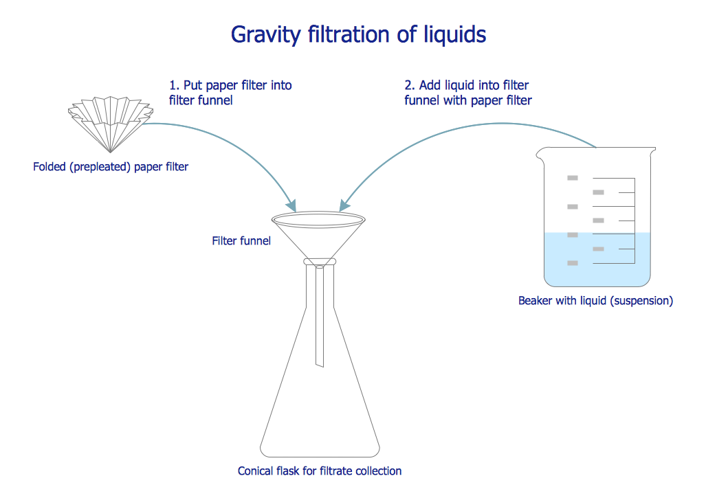
Picture: Chemistry Symbols and Meanings
Related Solution:
Active Directory Diagrams visualize the detailed structures of the Microsoft Windows networks, Active Directory Domain topology, the Active Directory Site topology, the Organizational Units (OU), and the Exchange Server Organization.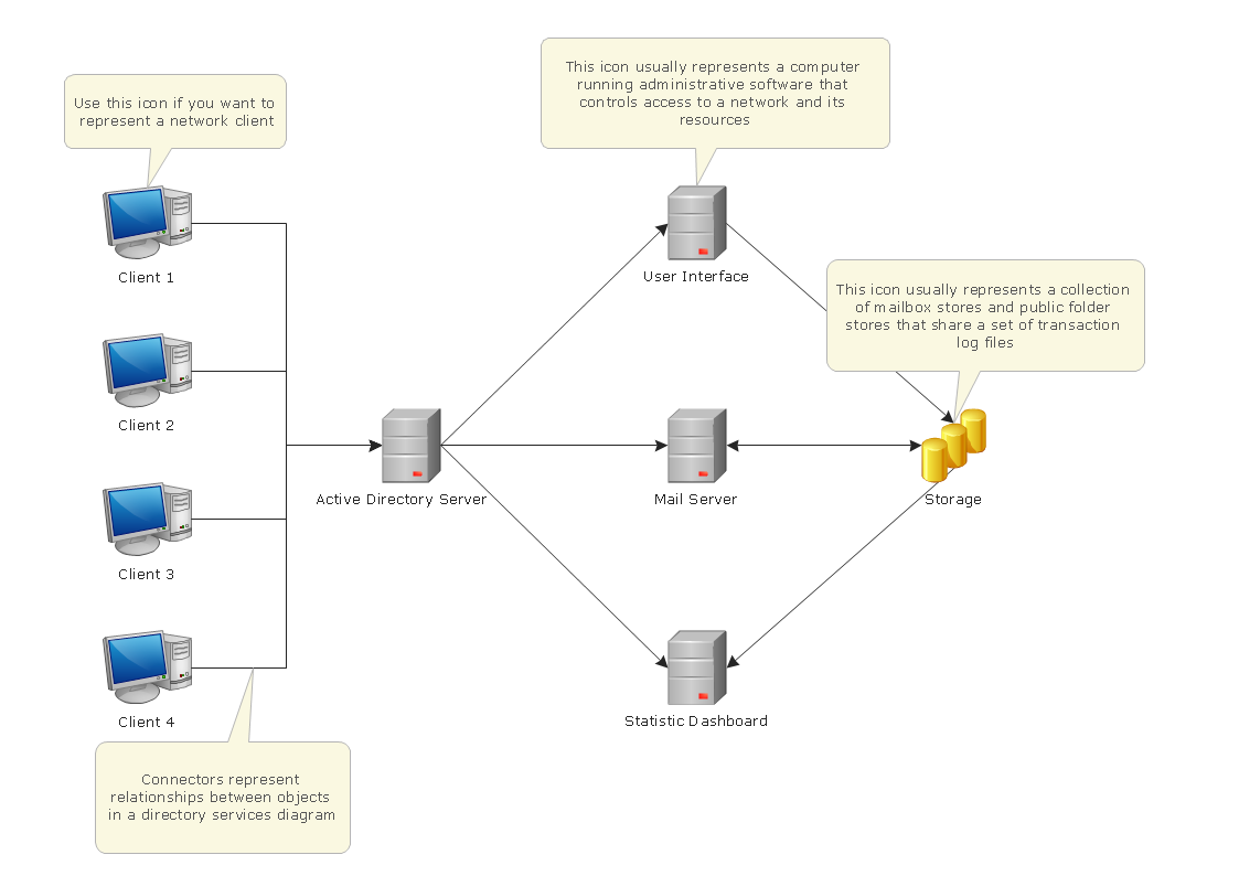
Picture: Active Directory Domain Services
ConceptDraw DIAGRAM diagramming and vector drawing software offers the Entity-Relationship Diagram (ERD) Solution from the Software Development Area for ConceptDraw Solution Park. How many examples contains the Entity-Relationship Diagram (ERD) Solution! All Entity Relationship Diagram examples were designed and saved for ConceptDraw DIAGRAM users. Now they are available from ConceptDraw STORE.
Picture: Entity Relationship Diagram Examples
Related Solution:
SIPOC is a tool that summarizes the inputs and outputs of one or more processes in table form.
You need to draw professional looking SIPOC Diagram quick and easy? Pay please your attention on ConceptDraw DIAGRAM diagramming and vector drawing software. Extended with Business Process Mapping Solution from the Business Processes Area of ConceptDraw Solution Park, it suits ideal for this.
Picture: SIPOC Diagram
Related Solution:
Develop of landscape drawing is a complex process which requires great efforts and inspiration. ConceptDraw DIAGRAM is a powerful diagramming and vector drawing software. Extended with Site Plans Solution from the Building Plans Area, ConceptDraw DIAGRAM will help to make this process easier.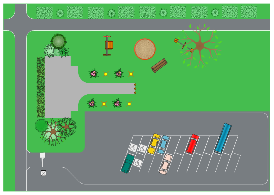
Picture: Landscape Drawing
Related Solution:
ConceptDraw DIAGRAM is a world-class diagramming platform that lets you display, communicate, and present dynamically. It′s powerful enough to draw everything from basic flowcharts to complex engineering schematics.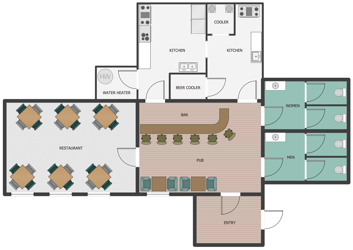
Picture: How to Draw a Building Plans
Related Solution:
ConceptDraw DIAGRAM diagramming and vector drawing software offers the Fault Tree Analysis Diagrams Solution from the Industrial Engineering Area of ConceptDraw Solution Park for quick and easy creating the Fault Tree Diagram of any degree of detailing.
Picture: Fault Tree Diagram
Related Solution:
When moving to a new apartment it is always pleasure to develop an interior design project. Nevertheless, another important part that should not be forgotten is the piping plan, because wrong piping system might ruin all the renovation. So, to avoid such problems, a stress analysis is performed.
Plumbing and piping plans should be created for any premises. They are used to trace location of pipes, fixtures and valves in the house. This diagram presents a set of certified piping plan symbols for drawing plumbing and piping floor plans, diagrams and other technical drawings. Applying standard symbols when creating a piping plan is very important for creating a valid piping plan included into the building documentation pack. It is essential for any professional to be able to read and properly interpreted any piping plan.
Picture: Interior Design. Piping Plan — Design Elements
Related Solution:
The Office Layout Plans Solution contains a large quantity of vector objects that will make your creating of the office design plans easy, quick and effective. It also provides templates and samples that will help you create the office designs of any difficulty in one moment.
Picture: Office Design Software
Related Solution: