Electrical Symbols, Electrical Diagram Symbols

This solution provides 26 libraries which contain 926 electrical symbols from electrical engineering: Analog and Digital Logic, Composite Assemblies, Delay Elements, Electrical Circuits, Electron Tubes, IGFET, Inductors, Integrated Circuit, Lamps, Acoustics, Readouts, Logic Gate Diagram, MOSFET, Maintenance, Power Sources, Qualifying, Resistors, Rotating Equipment, Semiconductor Diodes, Semiconductors, Stations, Switches and Relays, Terminals and Connectors, Thermo, Transformers and Windings, Transistors, Transmission Paths,VHF UHF SHF.
Electrical Drawing Software and Electrical Symbols

Electrical Drawing Software provides the 26 stencils libraries of ready-to-use predesigned vector electrical symbols, templates and samples that make your electrical drawing quick, easy and effective.
Electrical Symbols, Electrical Schematic Symbols

How to draw Metro Map style infographics? Moscow, New York, Los Angeles, London

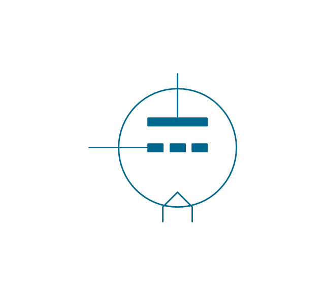
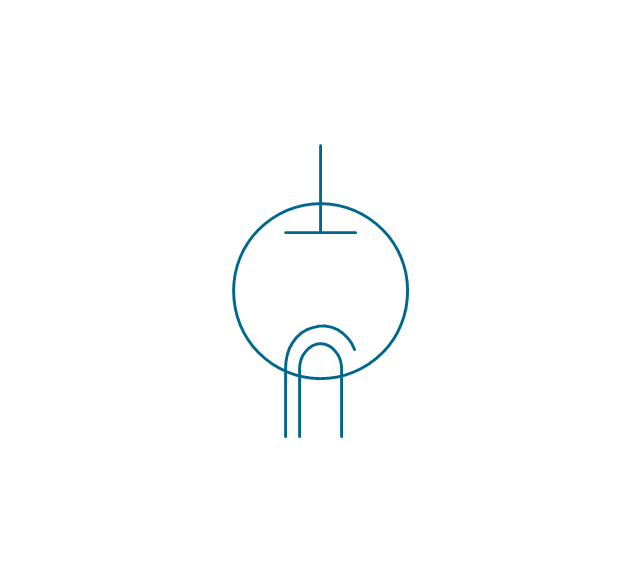
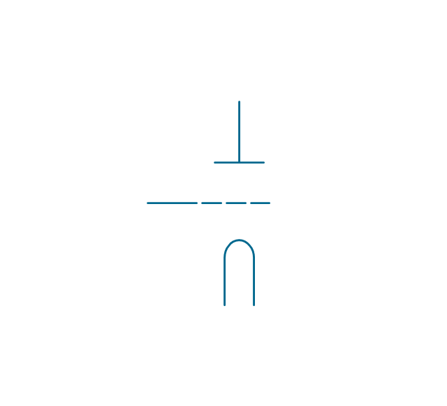
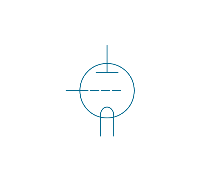
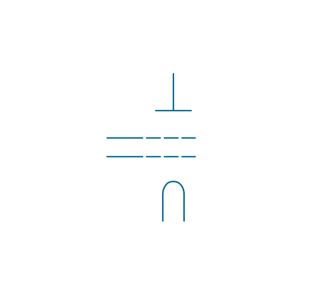
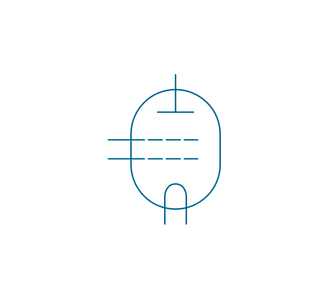
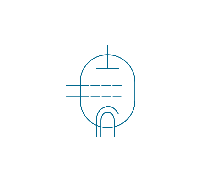
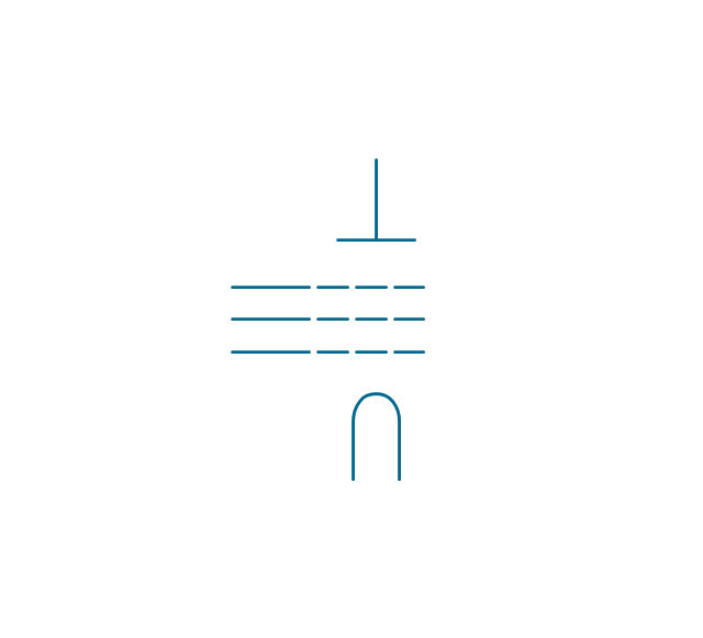
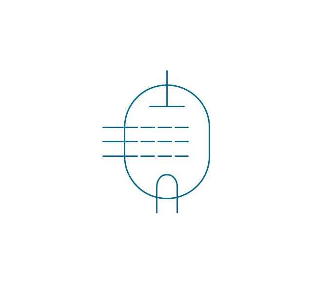
The vector stencils library "Design elements - Electron tubes" contains 36 element symbols of electron tubes.
Use it for drawing electrical schematics and electronic circuit diagrams.
"One classification of vacuum tubes is by the number of active electrodes, (neglecting the filament or heater). A device with two active elements is a diode, usually used for rectification. Devices with three elements are triodes used for amplification and switching. Additional electrodes create tetrodes, pentodes, and so forth, which have multiple additional functions made possible by the additional controllable electrodes.
Other classifications are:
(1) by frequency range (audio, radio, VHF, UHF, microwave),
(2) by power rating (small-signal, audio power, high-power radio transmitting),
(3) by design (e.g., sharp- versus remote-cutoff in some pentodes),
(4) by application (receiving tubes, transmitting tubes, amplifying or switching, rectification, mixing),
(5) special qualities (long life, very low microphonic and low noise audio amplification, and so on).
Multiple classifications may apply to a device; for example similar dual triodes can be used for audio preamplification and as flip-flops in computers, although linearity is important in the former case and long life in the latter.
Tubes have different functions, such as cathode ray tubes which create a beam of electrons for display purposes (such as the television picture tube) in addition to more specialized functions such as electron microscopy and electron beam lithography. X-ray tubes are also vacuum tubes. Phototubes and photomultipliers rely on electron flow through a vacuum, though in those cases electron emission from the cathode depends on energy from photons rather than thermionic emission." [Vacuum tube. Wikipedia]
The symbols example "Design elements - Electron tubes" was drawn using the ConceptDraw PRO diagramming and vector drawing software extended with the Electrical Engineering solution from the Engineering area of ConceptDraw Solution Park.
Vacuum tubes

Wiring Diagrams with ConceptDraw DIAGRAM

The vector stencils library "Electron tubes" contains 36 element symbols of electron tubes.
Use it for drawing electrical schematics and electronic circuit diagrams in the ConceptDraw PRO diagramming and vector drawing software extended with the Electrical Engineering solution from the Engineering area of ConceptDraw Solution Park.
www.conceptdraw.com/ solution-park/ engineering-electrical
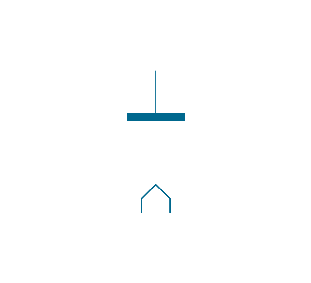
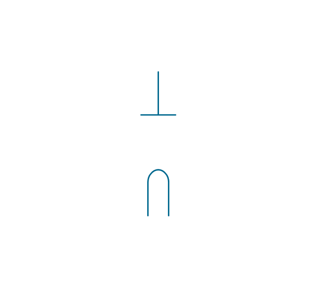
Diode, directly heated
Diode, indirectly heated
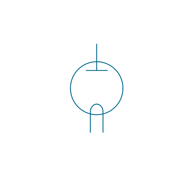
Diode, envelope, direct. heated
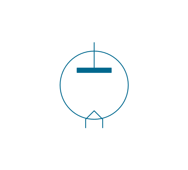
Diode, envelope, indirect. heated
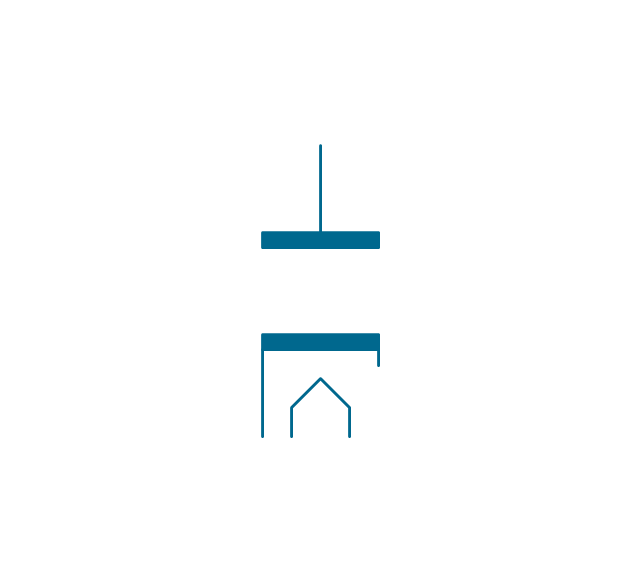
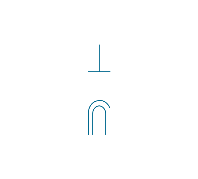
Triode, directly heated

Triode, indirectly heated

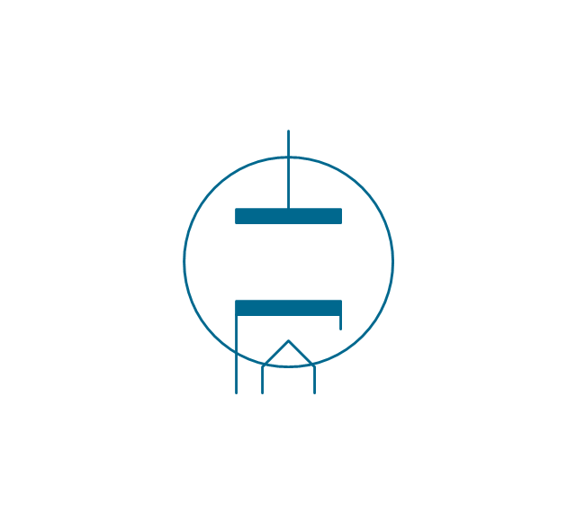
Triode, envelope, direct. heated
Triode, envelope, indirect. heated

Tetrode, directly heated

Tetrode, indirectly heated

Tetrode, envelope, direct. heated

Tetrode, envelope, indirect. heated

Pentode, directly heated

Pentode, indirectly heated, external connection

Pentode, indirectly heated, internal connection

Pentode, envelope, direct. heated

Pentode, envelope, indirect. heated, external connection

Pentode, envelope, indirect. heated, internal connection

Diode, directly heated 2
Diode, indirectly heated 2
Diode, envelope, direct. heated 2
Diode, envelope, indirect. heated 2
Triode, directly heated 2
Triode, indirectly heated 2

Triode, envelope, direct. heated 2
Triode, envelope, indirect. heated 2

Tetrode, directly heated 2
Tetrode, indirectly heated 2

Tetrode, envelope, direct. heated 2
Tetrode, envelope, indirect. heated 2
Pentode, directly heated 2
Pentode, indirectly heated, external connection 2

Pentode, indirectly heated, internal connection 2

Pentode, envelope, direct. heated 2
Pentode, envelope, indirect. heated, external connection 2

Pentode, envelope, indirect. heated, internal connection 2

Electrical Diagram

Swim Lane Flowchart Symbols

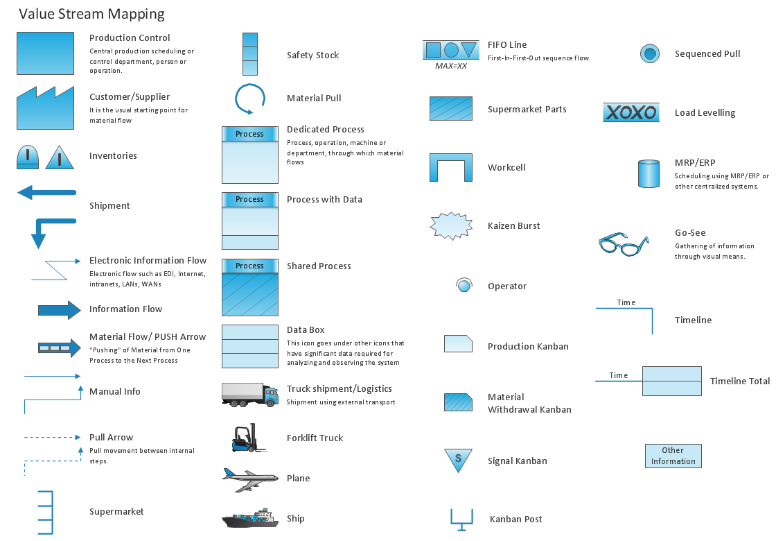
Value Stream Mapping Symbols
How to draw Metro Map style infographics? (Los Angeles)

This is a one-click tool to add stations to the map. It lets you control the direction in which you create new stations, change lengths, and add text labels and icons. It contains Lines, Stations, and Landmarks objects.
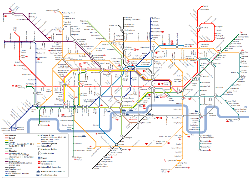
How to draw Metro Map style infographics? (London)
Electrical Symbols — Delay Elements

26 libraries of the Electrical Engineering Solution of ConceptDraw DIAGRAM make your electrical diagramming simple, efficient, and effective. You can simply and quickly drop the ready-to-use objects from libraries into your document to create the electrical diagram.
Electrical Symbols — Qualifying

26 libraries of the Electrical Engineering Solution of ConceptDraw DIAGRAM make your electrical diagramming simple, efficient, and effective. You can simply and quickly drop the ready-to-use objects from libraries into your document to create the electrical diagram.
Electrical Symbols — MOSFET

Although the MOSFET is a four-terminal device with source (S), gate (G), drain (D), and body (B) terminals, the body (or substrate) of the MOSFET is often connected to the source terminal, making it a three-terminal device like other field-effect transistors. Because these two terminals are normally connected to each other (short-circuited) internally, only three terminals appear in electrical diagrams. The MOSFET is by far the most common transistor in both digital and analog circuits, though the bipolar junction transistor was at one time much more common.
26 libraries of the Electrical Engineering Solution of ConceptDraw DIAGRAM make your electrical diagramming simple, efficient, and effective. You can simply and quickly drop the ready-to-use objects from libraries into your document to create the electrical diagram.
- What Are The Common Symbols And Draw The Electron Tube Symbol
- Electrical Drawing Software and Electrical Symbols | Electrical ...
- Design elements - Electron tubes | Electrical Symbols , Electrical ...
- Design elements - Electron tubes | Symbol Of Cathod Ray Tub For ...
- Electrical Drawing Software and Electrical Symbols | Electrical ...
- Symbol Of Tube Light In Drawing Sheet
- Electrical Drawing Software and Electrical Symbols | Electrical ...
- Engineering Drawing Tube Light Symbol
- Draw The Symbol Of Diode Tube
- Symbol Of Tube Starter In Engineering Drawing
- Symbol Of Tube Light In Engineering Drawing
- Design elements - Electron tubes | Electrical Symbols , Electrical ...
- Electrical Drawing Software and Electrical Symbols | Electrical ...
- Design elements - Electron tubes | Accounting Flowchart Symbols ...
- Draw Electronic Symbol Of A Tetrode
- Tube Map Symbols
- Vacuum Tube Circuit Diagrams
- Design elements - Electron tubes | Circuit diagram - EL 34 ...
- Electrical Symbols , Electrical Diagram Symbols | Electrical Drawing ...
- Tubes In The Pneumatic Symbols
- ERD | Entity Relationship Diagrams, ERD Software for Mac and Win
- Flowchart | Basic Flowchart Symbols and Meaning
- Flowchart | Flowchart Design - Symbols, Shapes, Stencils and Icons
- Flowchart | Flow Chart Symbols
- Electrical | Electrical Drawing - Wiring and Circuits Schematics
- Flowchart | Common Flowchart Symbols
- Flowchart | Common Flowchart Symbols