Electrical Symbols, Electrical Diagram Symbols

This solution provides 26 libraries which contain 926 electrical symbols from electrical engineering: Analog and Digital Logic, Composite Assemblies, Delay Elements, Electrical Circuits, Electron Tubes, IGFET, Inductors, Integrated Circuit, Lamps, Acoustics, Readouts, Logic Gate Diagram, MOSFET, Maintenance, Power Sources, Qualifying, Resistors, Rotating Equipment, Semiconductor Diodes, Semiconductors, Stations, Switches and Relays, Terminals and Connectors, Thermo, Transformers and Windings, Transistors, Transmission Paths,VHF UHF SHF.
Electrical Diagram

Electrical Drawing Software and Electrical Symbols

Electrical Drawing Software provides the 26 stencils libraries of ready-to-use predesigned vector electrical symbols, templates and samples that make your electrical drawing quick, easy and effective.
Electrical Symbols, Electrical Schematic Symbols

Wiring Diagrams with ConceptDraw DIAGRAM

Anyone Have an ERD Symbols Quick Reference?

But anyone have an ERD symbols quick reference? Detailed reference information for them is represented at the tables.
Chemistry Drawings
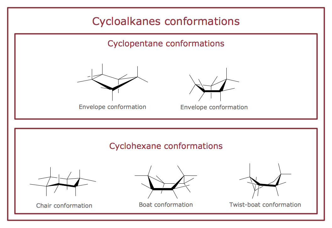
that can be then successfully used in the field of science and education, on various conferences, and so on.
Circuits and Logic Diagram Software

Electrical Engineering solution helps you create quick and easy: Electrical schematics, Digital and analog logic designs, Circuit and wiring schematics and diagrams, Power systems diagrams, Maintenance and repair diagrams, Circuit board and amplifier diagrams, Integrated circuit schematics.
Electrical Symbols — Delay Elements

26 libraries of the Electrical Engineering Solution of ConceptDraw DIAGRAM make your electrical diagramming simple, efficient, and effective. You can simply and quickly drop the ready-to-use objects from libraries into your document to create the electrical diagram.
UML Block Diagram

This sample shows the work of the taxi service and is used by taxi stations, by airports, in the tourism field and delivery service.
Finite State Machine

Chemical Engineering

HelpDesk
How to Create a Fault Tree Analysis Diagram (FTD)

- All Logic Gate Circuit
- American Symbols For All The Logic Gates
- Logic gate diagram - Template | Engineering | Electrical Drawing ...
- Logic gate diagram - Template
- Logic gate diagram
- Design elements - Logic gate diagram | Electrical Drawing Software ...
- Logic gate diagram - Template | Electrical Symbols , Electrical ...
- Design elements - Logic gate diagram | How to Create a Fault Tree ...
- Design elements - Logic gate diagram | Electrical Symbols — Logic ...
- 2-bit ALU - Logic gate diagram | Electrical Symbols , Electrical ...
- Logic Gate Drawer
- Logic Gate Symbol
- Circuits and Logic Diagram Software | Electrical Drawing Software ...
- Design elements - Logic gate diagram
- Logic gate diagram - Template | Circuits and Logic Diagram ...
- Design elements - Logic gate diagram | Electrical Symbols ...
- Electrical Drawing Software and Electrical Symbols | Circuits and ...
- Electrical Drawing Software | Design elements - Logic gate diagram ...
- Logic gate diagram - Template | Design elements - Logic gate ...
- Best Software To Draw Logic Gates
- ERD | Entity Relationship Diagrams, ERD Software for Mac and Win
- Flowchart | Basic Flowchart Symbols and Meaning
- Flowchart | Flowchart Design - Symbols, Shapes, Stencils and Icons
- Flowchart | Flow Chart Symbols
- Electrical | Electrical Drawing - Wiring and Circuits Schematics
- Flowchart | Common Flowchart Symbols
- Flowchart | Common Flowchart Symbols