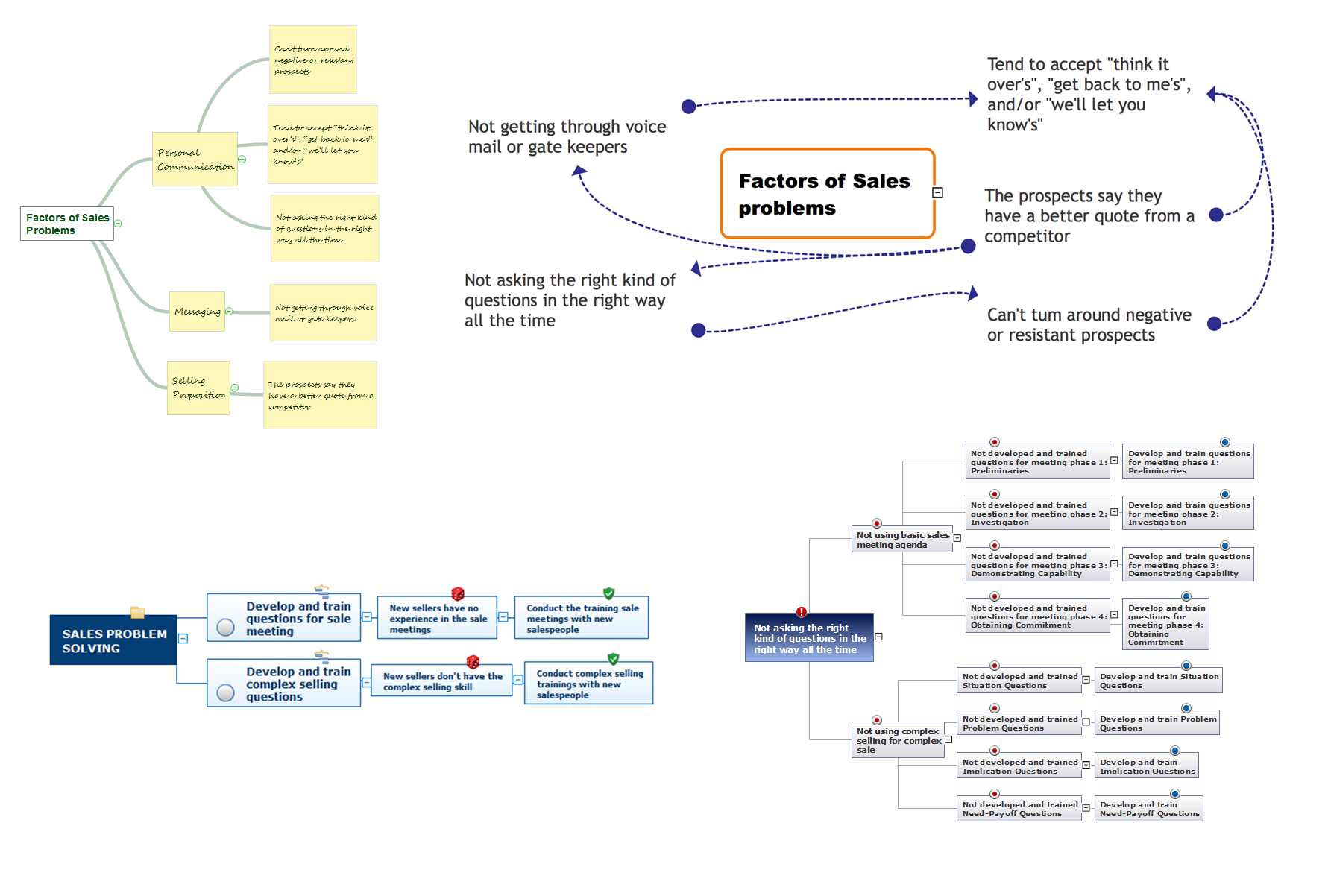
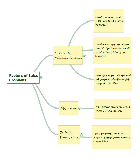
PROBLEM ANALYSIS. Identify and Structure Factors


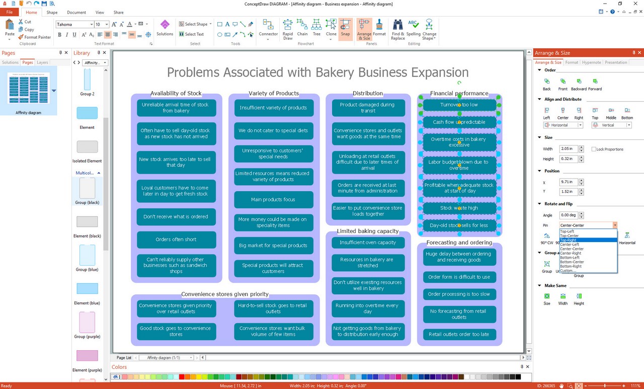
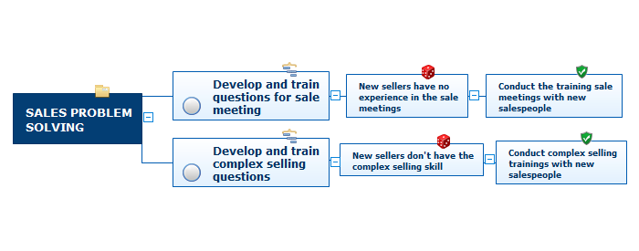
Affinity Diagram Software
Risk Diagram (Process Decision Program Chart)
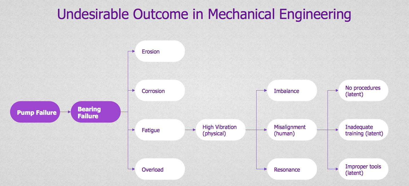
Root Cause Tree Diagram

7 Management & Planning Tools
Affinity Diagram
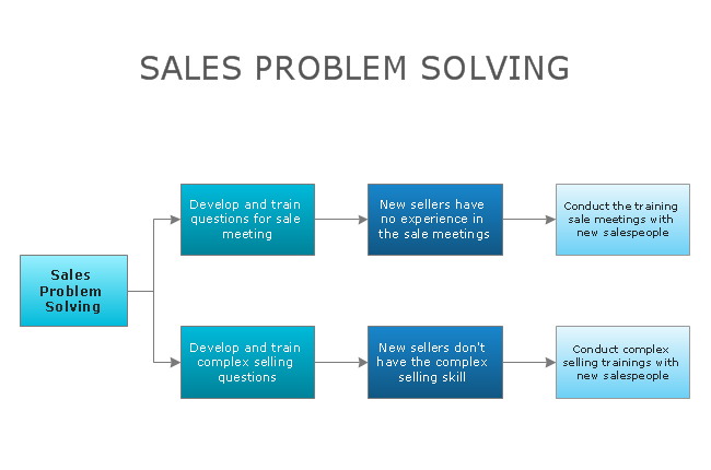
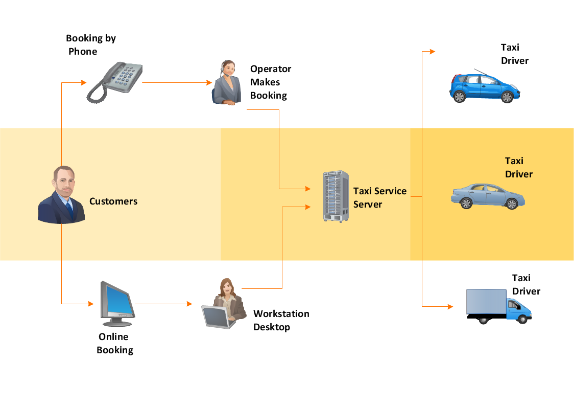
Workflow Diagram
House of Quality Matrix Software

Risk Diagram (Process Decision Program Chart)
UML Sample Project

 Seven Management and Planning Tools
Seven Management and Planning Tools solution extends ConceptDraw DIAGRAM and ConceptDraw MINDMAP with features, templates, samples and libraries of vector stencils for drawing management mind maps and diagrams.
Activity Network Diagram Method

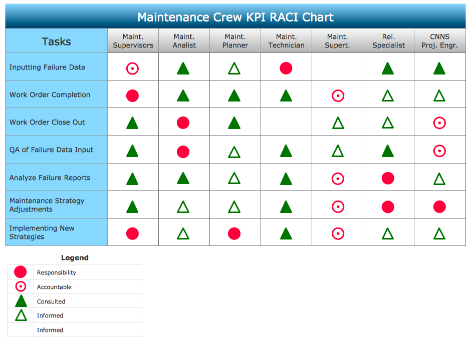
Authority Matrix Diagram Software
PROBLEM ANALYSIS. Root Cause Analysis Tree Diagram
Developing Entity Relationship Diagrams

- PDPC | Risk diagram ( PDPC ) - Template | Process decision ...
- Top 5 Android Flow Chart Apps | CORRECTIVE ACTIONS ...
- CORRECTIVE ACTIONS PLANNING. Risk Diagram ( PDPC ...
- CORRECTIVE ACTIONS PLANNING. Risk Diagram ( PDPC ) | Top 5 ...
- Risk Diagram (Process Decision Program Chart ) | Process decision ...
- How To Create Risk Diagram ( PDPC )
- PDPC | Preventive Action | Process decision program chart ( PDPC ...
- Process decision program chart ( PDPC ) - Personal activity | PDPC ...
- Risk Diagram (Process Decision Program Chart ) | PDPC | Risk ...
- PDPC | PERT Chart Software | Bar Diagrams for Problem Solving ...
- Relationships Analysis | Healthy Food Ideas | CORRECTIVE ...
- Pert Chart Images
- Preventive Action Chart
- CORRECTIVE ACTIONS PLANNING. Risk Diagram ( PDPC ) | The ...
- CORRECTIVE ACTIONS PLANNING. Risk Diagram ( PDPC ) | How ...
- Problem Analysis Vs Decision Making In Chart
- Pictures of Graphs | Create Graphs and Charts | BPR Diagram ...
- CORRECTIVE ACTIONS PLANNING. Risk Diagram ( PDPC ...
- Influence Diagram Software | Workflow Diagram | Risk diagram ...
- Hd Images For Decision Making Process