Finite State Machine
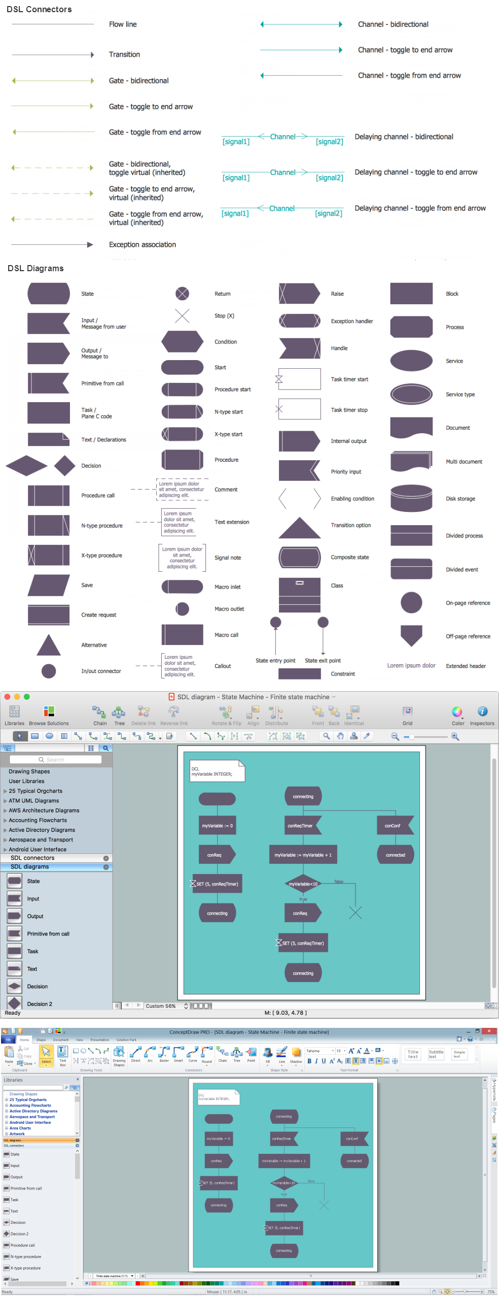
You need design a Finite State Machine (FSM) diagram and dream to find a powerful software to make it easier? ConceptDraw PRO extended with Specification and Description Language (SDL) Solution from the Engineering Area of ConceptDraw Solution Park is the best software for achievement this goal.FSM — Finite-state Machine
ConceptDraw PRO diagramming and vector drawing software extended with Specification and Description Language (SDL) Solution from the Engineering Area of ConceptDraw Solution Park provides powerful drawing tools for quick and easy creating well-designed FSM diagrams.State Machine Diagram
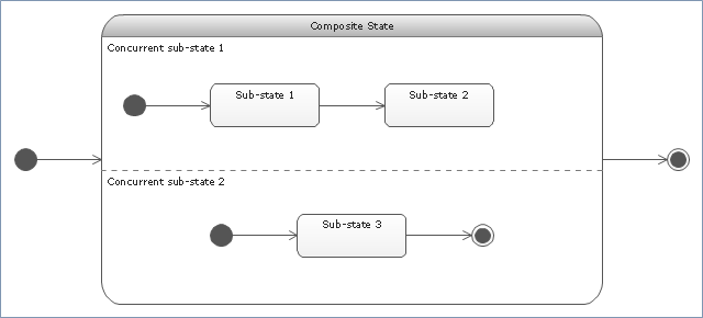
UML state machine's goal is to overcome the main limitations of traditional finite-state machines while retaining their main benefits. ConceptDraw is ideal for software designers and software developers who need to draw UML State Machine Diagrams.
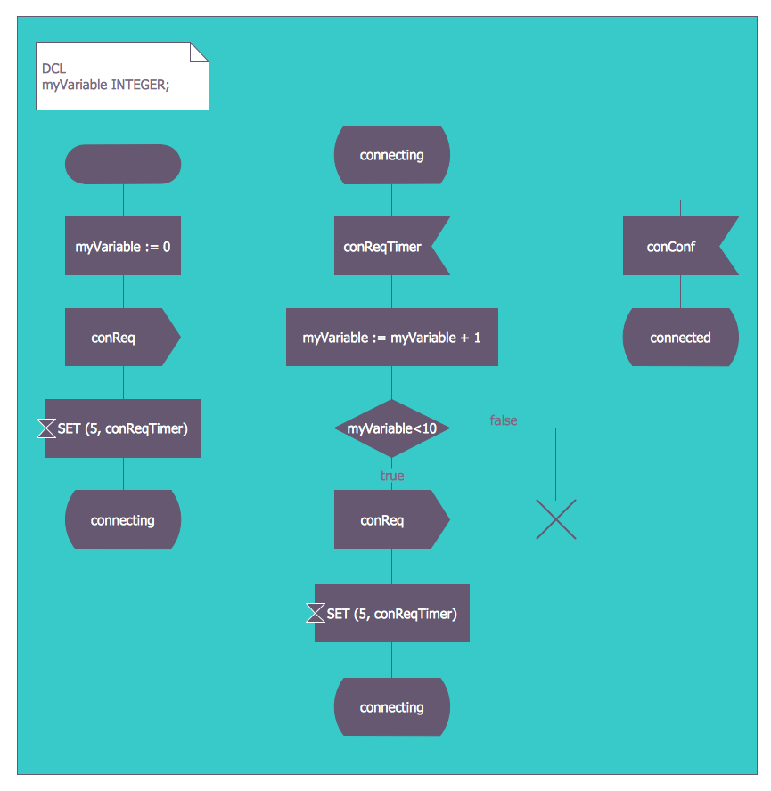
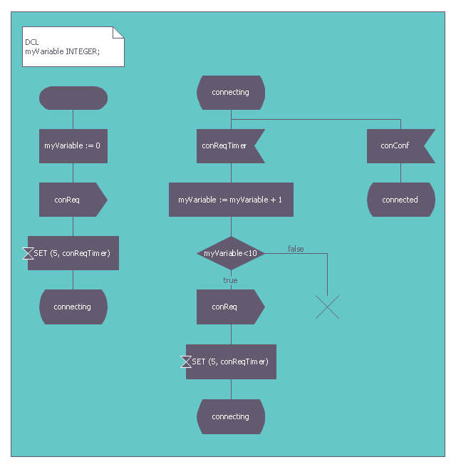
This finite state machine diagram example was redesigned from the Wikimedia Commons file: SdlStateMachine.png. [commons.wikimedia.org/ wiki/ File:SdlStateMachine.png]
This file is licensed under the Creative Commons Attribution-Share Alike 3.0 Unported license. [creativecommons.org/ licenses/ by-sa/ 3.0/ deed.en]
"Behavior.
Each process agent is a state machine that contributes to the action carried out by the system. A message stimulus coming from the environment or from another agent to an agent is called a signal. Signals received by a process agent are first placed in a queue (the input port). When the state machine is waiting in a state, if the first signal in the input port is enabled for that state it starts a transition leading to another state. Transitions can output signals to other agents or to the environment. A process agent is allowed to contain procedure types so that the same actions can be invoked from different places. It is also allowed to call a remote procedure type to invoke a procedure in another agent (or even another system) and wait for a response." [Specification and Description Language. Wikipedia]
The example "SDL diagram - State Machine" was created using the ConceptDraw PRO diagramming and vector drawing software extended with the Specification and Description Language (SDL) solution from the Engineering area of ConceptDraw Solution Park.
Used Solutions
Diagramming Software for Design UML State Machine Diagrams
UML state machine's goal is to overcome the main limitations of traditional finite-state machines while retaining their main benefits.
UML State Machine Diagram.Design Elements
UML state machine's goal is to overcome the main limitations of traditional finite-state machines while retaining their main benefits. ConceptDraw has 393 vector stencils in the 13 libraries that helps you to start using software for designing your own UML Diagrams. You can use the appropriate stencils of UML notation from UML State Machine library."State machine diagram is a behavior diagram which shows discrete behavior of a part of designed system through finite state transitions. State machine diagrams can also be used to express the usage protocol of part of a system. Two kinds of state machines defined in UML 2.4 are:
(1) behavioral state machine, and
(2) protocol state machine.
The following nodes and edges are typically drawn in state machine diagram: behavioral state, behavioral transition, protocol state, protocol transition, different pseudostates. ...
Behavioral state machine is specialization of behavior and is used to specify discrete behavior of a part of designed system through finite state transitions. The state machine formalism used in this case is an object-based variant of Harel statecharts.
Behavior is modeled as a traversal of a graph of state nodes connected with transitions. Transitions are triggered by the dispatching of series of events. During the traversal, the state machine could also execute some activities. ...
Protocol state machine is a specialization of behavioral state machine and is used to express usage protocol or lifecycle of a classifier. It specifies which operations of the classifier can be called in which state and under which condition, thus specifying the allowed call sequences on the classifier’s operations. Protocol state machines express the legal transitions that a classifier can trigger." [uml-diagrams.org/ state-machine-diagrams.html]
The template "UML state machine diagram" for the ConceptDraw PRO diagramming and vector drawing software is included in the Rapid UML solution from the Software Development area of ConceptDraw Solution Park.
www.conceptdraw.com/ solution-park/ software-uml
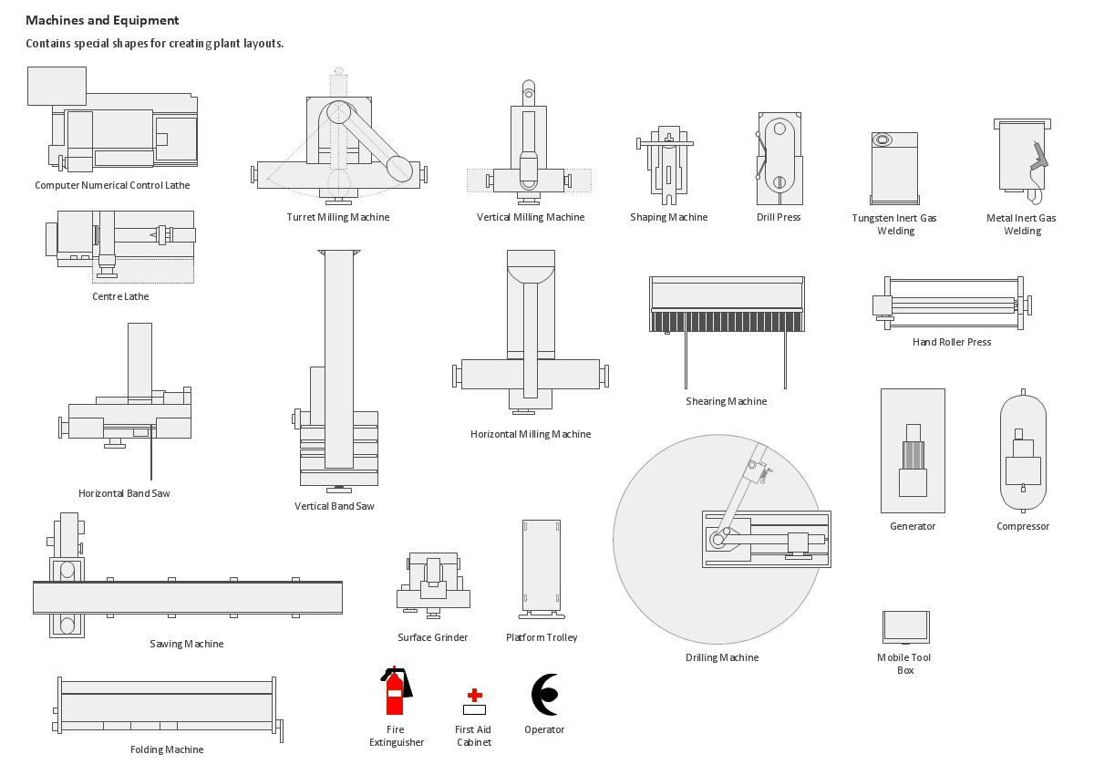
Building Drawing Design Element: Machines and Equipment
Use ConceptDraw to develop the plant layouts for production, storage, distribution, transport, shipping, and receiving of manufactured goods.
State Diagram Example - Online Store
This sample was created in ConceptDraw PRO diagramming and vector drawing software using the UML State Mashine Diagram library of the Rapid UML Solution from the Software Development area of ConceptDraw Solution Park. This sample shows the work of the online store and can be used for the understanding of the online shopping processes, for projection and creating of the online store.Detail Specifications Exchanging Mind Maps with Evernote
ConceptDraw Note Exchange Solution permits users to develop and organize notes and tasks in ConceptDraw MINDMAP. Your work can be accessed later, just with one click, regardless of preferred platform.
 Specification and Description Language (SDL)
For people in the field of systems engineering or system design, working with specification and description language (sdl) and finite state machines (fsm).
BPMN 2.0
ConceptDraw PRO diagramming and vector drawing software offers the Business Process Diagram Solution from the Business Processes Area of ConceptDraw Solution Park with powerful tools to help you easy represent the business processes and create the business process diagrams based on BPMN 2.0 standard.UML Diagram for Mac
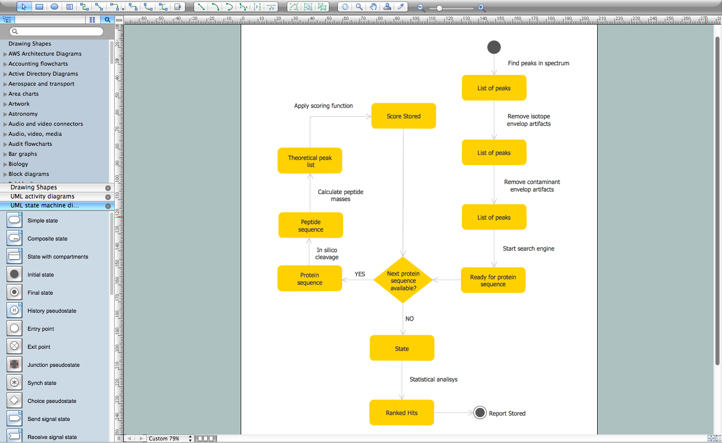
This sample was created on the Mac in ConceptDraw PRO diagramming and vector drawing software using the UML State Machine Diagram library of the Rapid UML Solution from the Software Development area of ConceptDraw Solution Park.UML Activity Diagram. Design Elements
UML Activity Diagram illustrate the business and operational step-by-step workflow of components in a system and shows the overall flow of control.
Systems Engineering
Systems engineering is an interdisciplinary field of engineering that focuses on how to design and manage complex engineering systems over their life cycles. ConceptDraw PRO supplied with SysML Solution from the Software Development Area of ConceptDraw Solution Park is a powerful and effective systems engineering software.- Finite State Machine | State Machine Diagram | Systems ...
- Finite State Machine | UML State Machine Diagram.Design ...
- FSM — Finite - state Machine | UML State Machine Diagram.Design ...
- Finite State Machine Of Library Management System
- Finite State Machine Designer Online
- FSM — Finite - state Machine | UML Diagram Types List | Finite State ...
- Finite State Machine | Specification and Description Language (SDL ...
- UML state machine diagram - Template | FSM — Finite-state ...
- Finite State Machine Problems And Solutions
- Fsm Design Software
- Finite State Machine Mechanical Engineering
- Mechanical Drawing Symbols | FSM — Finite - state Machine ...
- FSM — Finite - state Machine | Electrical Engineering | Network ...
- FSM — Finite - state Machine | Flow Chart In Circulation Procedure
- State Diagram Example - Online Store | State Machine Diagram ...
- Diagramming Software for Design UML State Machine Diagrams ...
- Fsm Sdl
- Process Flowchart | FSM — Finite - state Machine | Cross-Functional ...
- Bank UML Diagram | State Machine Diagram | How to Create a ...
