BPMN 2.0
Using “Business Process Model and Notation” (or “BPMN”) is known to be a standard way of modelling the business processes, providing a graphical notation for specifying them on the Business Process Diagram, which can be made in ConceptDraw DIAGRAM within a few hours, sometimes — minutes. The mentioned diagram is based on the same technique, that is used for making flowcharts. Business Process Diagram is very similar to so-called “activity diagrams” with the use of Unified Modelling Language. The main aim of using BPMN is to support business processes within the management activity. It can be used both by business users as well as technical users in a way of providing a notation, which is intuitive to business users, being able to represent any complex process schematics.
The specification of BPMN allows providing a mapping between the graphics of the notation and the underlying constructs of execution languages. To manage to provide a standard notation in order for all the business stakeholders to understand it, you can always use “BPMN” creating the diagrams you need with the help of ConceptDraw DIAGRAM diagramming and drawing software. Not being a professional business analyst, you can still create and refine all the needed processes, and not being a technical developer who is responsible for the proper implementing, you can still always succeed in completing your tasks with ConceptDraw DIAGRAM as well as ConceptDraw STORE. If you have no experience in making any similar to the mentioned diagrams, you can still draw them using the provided solutions from ConceptDraw STORE which is an application available to be downloaded from this site.
To become a business manager, responsible for monitoring and managing any business processes with the aid of the appropriate software it is never a problem as long as you have ConceptDraw DIAGRAM and ConceptDraw STORE — another product of CS Odessa, developed for a purpose of providing the needed solutions to the ConceptDraw DIAGRAM users, such as a “Business Process Diagram” one, enabling you to make any needed Business Process Diagram.
BPMN is known to be serving as a common language, bridging the communication gap, which can sometimes occur between business process implementation and business process design. Nowadays there are a few competing standards for previously mentioned business process modelling languages used by the special modelling tools as well as the processes. BPMN is able to support only the concepts of modelling applicable to business processes, while other types of modelling, which are used by organizations for non-process purposes, are out of scope for BPMN.
The examples of modelling excluded from BPMN can be data models, organizational structures and the functional breakdowns. As long as the association of data artefacts to activities and BPMN shows the flow of data, it is not a data flow diagram, but if you need to create such data flow diagram — you can always do it with ConceptDraw DIAGRAM software.
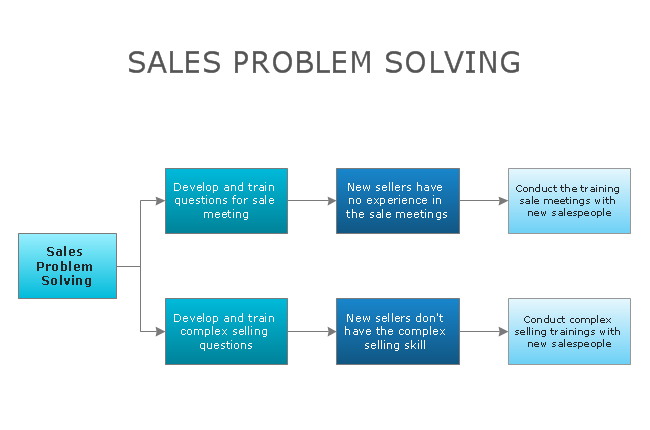
All “BPMN models” are known to consist of simple diagrams, which are created with a use of usually a simply limited set of graphical elements. For both business users as well as business developers, ConceptDraw DIAGRAM can be useful in order to simplify the understanding of the business activities, process and data flows. The well-known four BPMN's basic element categories enable the creation of simple business process diagrams. They are flow and connecting objects, swim lanes as well as artefacts, which are simply data object, annotation and group, activities, events, gateways, association, message flow and sequence flow, as well as pools and lanes.
You can always model any of the types of business processes with BPMN, such as “high-level private process activities” and “detailed private business processes”, so-called “to-be” or simply “new business processes”, “relationship to Abstract” processes, “old business processes”, “abstract” ones as well as “abstract process relationships”, “collaboration processes”, etc. Having enough professional tools for making the great as well as professionally looking drawings will enable you to get a smart and good-looking result within only a few hours, sometimes an hour or even up to a few minutes as long as you know ConceptDraw DIAGRAM software well enough and in case you have the right solution, downloaded from ConceptDraw STORE to use the existing pre-made examples as the drafts for your schematics.
The mentioned business process modelling can be used for communicating lots of information to lots of different people. BPMN was designed especially for covering this wide range of usage, allowing modelling the end-to-end business processes to allow the viewer of the created diagram to be able to simply differentiate between sections of any BPMN Diagram created in ConceptDraw DIAGRAM application. There are three basic types of sub-models within an end-to-end BPMN model, which are Abstract (also known as “public”) processes, Private (also called “internal”) business processes and Collaboration (or “global”) processes. And they all can be mentioned while creating the BPMN Diagram with the help of ConceptDraw DIAGRAM software.
Thus, taking into consideration that the well-known ConceptDraw DIAGRAM application was developed especially for a purpose of providing the convenience for macOS as well as Windows operating system users, you can always create any needed diagram, including the Business Process one, with the aid of the needed solution (for making Business Process Diagram it is always better to use the “Business Process Diagram Solution”). Once you need to make some drawing quick to get simply a great and professionally looking result, then you can always download the needed solution, such as Business Process Diagram one, in order to finish with your drawing within only a short period of time.
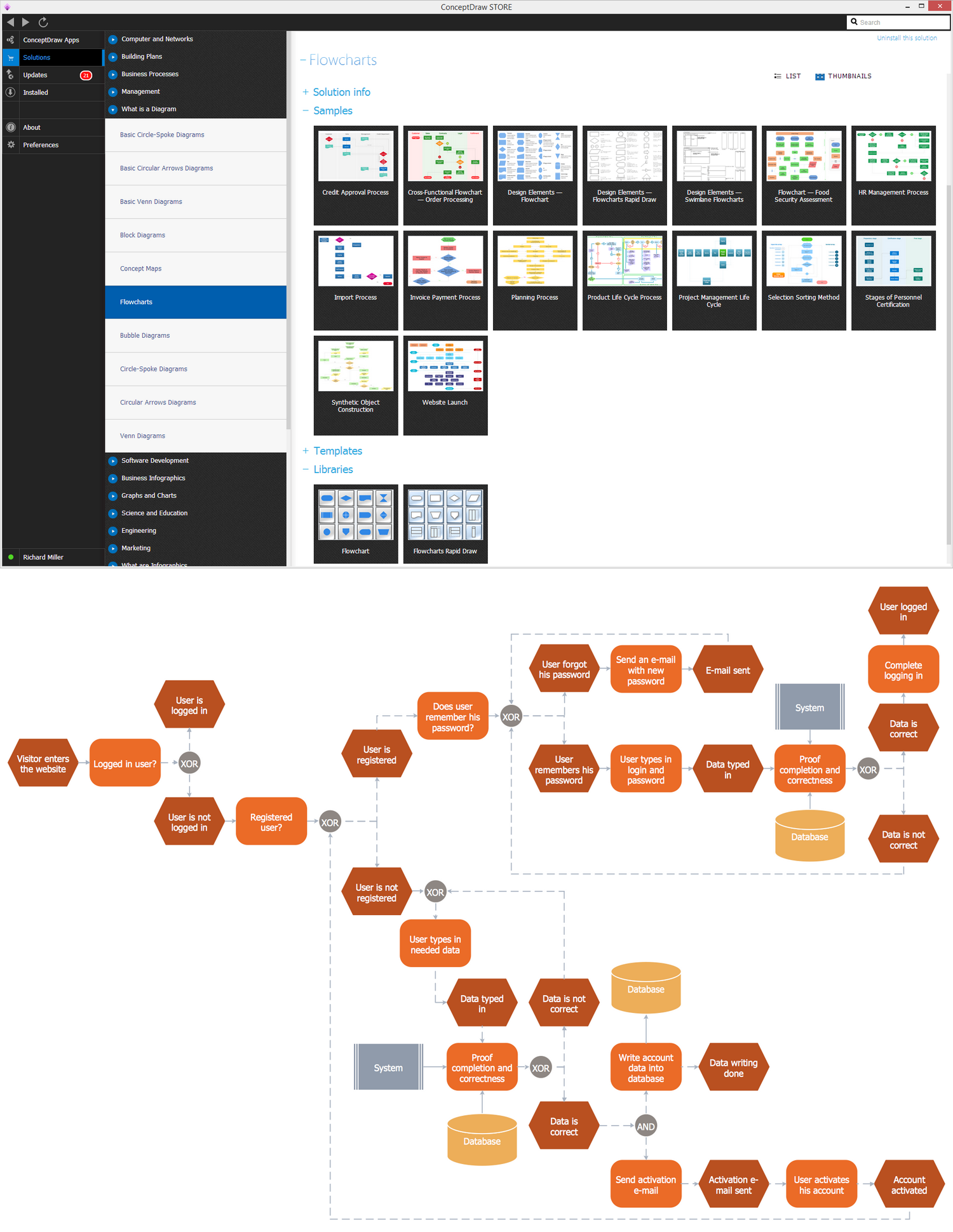
The mentioned Business Process Diagram Solution can be found in ConceptDraw STORE software and so to get the powerful tools to help you represent the business processes as well as to create the business process diagrams based on BPMN 2.0 standard.
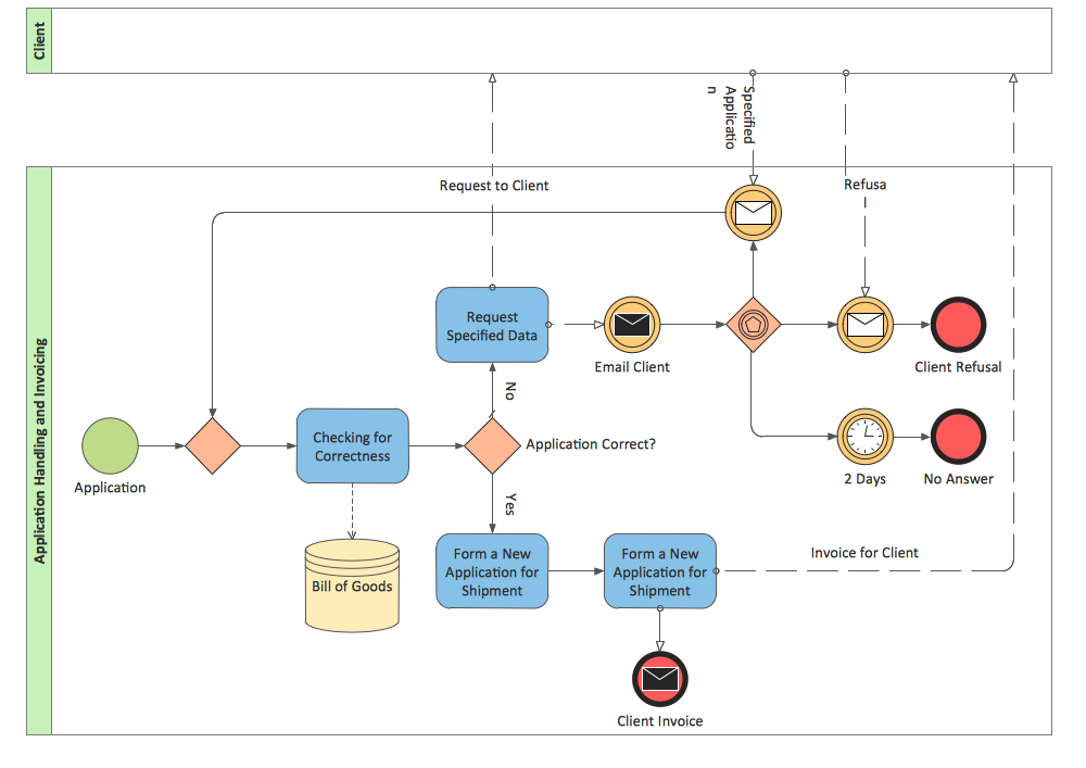
Example 1. BPMN 2.0 Diagram — Application Handling and Invoicing
Business Process Diagram Solution offers the extensive drawing tools and wide set of samples and templates. They were developed specially for ConceptDraw DIAGRAM users and are available from ConceptDraw STORE. Use them to facilitate your BPMN 2.0 Diagrams creating.

Example 2. Business Process Diagram Solution in ConceptDraw STORE
Business Process Diagram Solution includes also a set of libraries with ready-to-use vector shapes which conform to BPMN 2.0 standard:
- Activities
- Business Process - Rapid Draw
- Choreographies
- Conversations
- Data
- Events
- Expanded Objects
- Gateways
- Swimlanes
 Activities symbols library
 Business Process Diagram symbols library
 Choreographies symbols library
 Conversations symbols library
 Data symbols library
 Events symbols library
 Expanded Objects symbols library
 Gateways symbols library
 Swimlanes symbols library
Nothing can be easy than drag ready objects from the libraries and simply arrange them at the document.

Example 3. BPMN 2.0 Diagram - Advertising Creation Process
The samples you see on this page were created in ConceptDraw DIAGRAM using the objects from the libraries of Business Process Diagram Solution. An experienced user spent 5 minutes creating every of these BPMN 2.0 Diagrams.
Use the tools of Business Process Diagram Solution for ConceptDraw DIAGRAM software to quick and easy develop any business processes.
All source documents are vector graphic documents. They are available for reviewing, modifying, or converting to a variety of formats (PDF file, MS PowerPoint, MS Visio, and many other graphic formats) from the ConceptDraw STORE. The Business Process Diagram Solution is available for all ConceptDraw DIAGRAM or later users.