Accounting Flowchart Symbols

Gane Sarson Diagram

Business Process Flowchart Symbols

Entity Relationship Diagram Symbols

IDEF0 Flowchart Symbols

Swim Lane Flowchart Symbols

ERD Symbols and Meanings


The vector stencils library "Logical symbols" contains 49 logical symbols for drawing logical network topology diagrams.
"Logical topology, or signal topology, is the arrangement of devices on a computer network and how they communicate with one another. How devices are connected to the network through the actual cables that transmit data, or the physical structure of the network, is called the physical topology. Physical topology defines how the systems are physically connected. It represents the physical layout of the devices on the network. The logical topology defines how the systems communicate across the physical topologies.
Logical topologies are bound to network protocols and describe how data is moved across the network. ... EXAMPLE : twisted pair Ethernet is a logical bus topology in a physical star topology layout. While IBM's token ring is a logical ring topology, it is physically set up in star topology." [Logical topology. Wikipedia]
The icons example "Logical symbols - Vector stencils library" was created using the ConceptDraw PRO diagramming and vector drawing software extended with the Computer and Networks solution from the Computer and Networks area of ConceptDraw Solution Park.
www.conceptdraw.com/ solution-park/ computer-and-networks
Coaxial Line Tag

Fiber Optic Line Tag

Twisted Pair Line Tag

SC2200 Signaling Controller

Bridge

Network Management Appliance

Access Server (Communications Server)
-logical-symbols---vector-stencils-library.png--diagram-flowchart-example.png)
Terminal Server

Web Browser

Security Management, Cisco

Lock and Key

Lock

Key

Relational Database

Host

CSU/DSU

WAN

University

Government building

Home Office

Telecommuter House PC

Medium Building, Regular

Headquarters, Subdued

House, Regular

Small Business

Network Connector

Dynamic Connector

Line Connector

Line-curve Connector

Bus

FDDI Ring

Peer-to-peer

Token-ring

Star

Comm-link

Curved Bus

Ethernet

Cloud

Speaker

Microphone

Router

ATM Router

ISDN Switch

ATM Switch

ATM/FastGB Etherswitch

Workgroup Switch

Small Hub

100BaseT Hub

CDDI-FDDI

The vector stencils library "Network hardware" contains 27 clipart images and symbols of network equipment for drawing computer network diagrams.
"Networking hardware may also be known as network equipment or computer networking devices. Units which are the last receiver or generate data are called hosts or data terminal equipment.
All these terms refer to devices facilitating the use of a computer network. Specifically, they mediate data in a computer network. ...
Typically, networking hardware includes gateways, routers, network bridges, switches, hubs, and repeaters. But it also includes hybrid network devices such as multilayer switches, protocol converters, bridge routers, proxy servers, firewalls, network address translators, multiplexers, network interface controllers, wireless network interface controllers, modems, ISDN terminal adapters, line drivers, wireless access points, networking cables and other related hardware.
The most common kind of networking hardware today is a copper-based Ethernet adapter because of its standard inclusion on most modern computer systems. Wireless networking has, however, become increasingly popular, especially for portable and handheld devices.
Other hardware prevalent in computer networking includes data center equipment (such as file servers, database servers and storage areas), network services (such as DNS, DHCP, email, etc.) as well as devices which assure content delivery.
Taking a wider view, mobile phones, PDAs and even modern coffee machines may also be considered networking hardware. As technology advances and IP-based networks are integrated into building infrastructure and household utilities, network hardware will becomes an ambiguous term owing to the vastly increasing number of "network capable" endpoints." [Networking hardware. Wikipedia]
The clip art example "Network hardware -Vector stencils library" was created using the ConceptDraw PRO diagramming and vector drawing software extended with the Computer and Networks solution from the Computer and Networks area of ConceptDraw Solution Park.
www.conceptdraw.com/ solution-park/ computer-and-networks
Rack
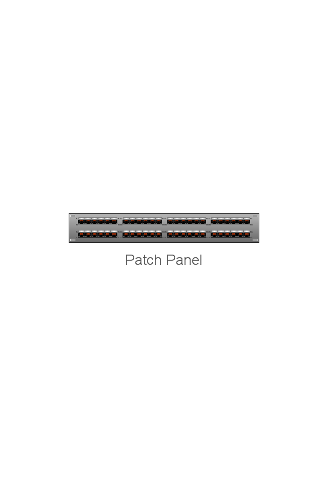
Patch Panel 48
Modem
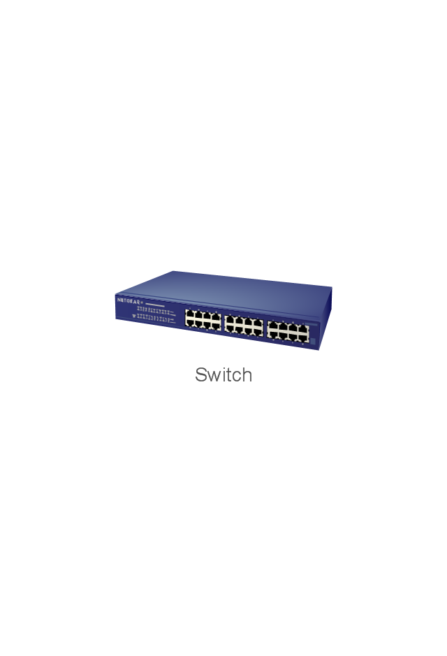
Switch
Hub

Router
AirPort Extreme
Xserve RAID
Server
Server
RAID Drive
Patch bay
UPS
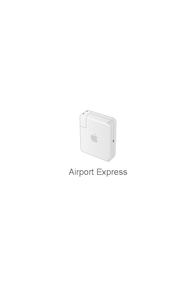
Airport Express
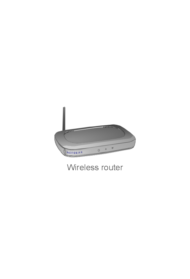
Wireless router
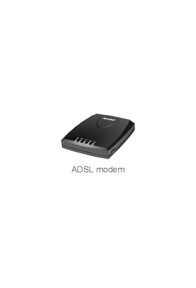
ADSL modem
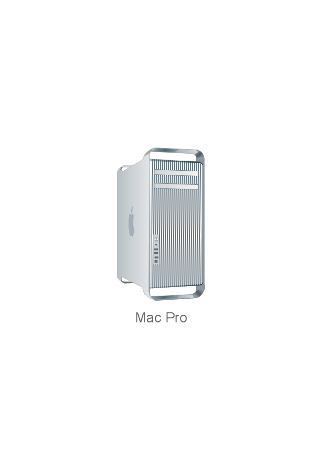
Mac Pro
Power Mac G5
Power Mac G4 Cube
XServe
Patch Panel 24
AirPort Extreme/ Time Capsule
Switch (8 port)
-network-hardware---vector-stencils-library.png--diagram-flowchart-example.png)
Switch (16 port)
-network-hardware---vector-stencils-library.png--diagram-flowchart-example.png)
Switch (24 port)
-network-hardware---vector-stencils-library.png--diagram-flowchart-example.png)
Switch (48 port)
-network-hardware---vector-stencils-library.png--diagram-flowchart-example.png)
Patch Panel (24 port)
-network-hardware---vector-stencils-library.png--diagram-flowchart-example.png)
Notation & Symbols for ERD

The vector stencils library "HR flowchart" contains 62 flowchart symbols.
Use it to draw your HR flowcharts, workflow diagrams and process charts with the ConceptDraw PRO diagramming and vector drawing software.
The flow chart symbols library "HR flowchart" is included in the HR Flowcharts solution from the Management area of ConceptDraw Solution Park.
Use it to draw your HR flowcharts, workflow diagrams and process charts with the ConceptDraw PRO diagramming and vector drawing software.
The flow chart symbols library "HR flowchart" is included in the HR Flowcharts solution from the Management area of ConceptDraw Solution Park.
Annotation
Card

Check / audit (diamond)
-hr-flowchart---vector-stencils-library.png--diagram-flowchart-example.png)
Check / audit (square)
-hr-flowchart---vector-stencils-library.png--diagram-flowchart-example.png)
Collate

Comment / note symbol (brace)
-hr-flowchart---vector-stencils-library.png--diagram-flowchart-example.png)
Communication link
Compare (diamond)
-hr-flowchart---vector-stencils-library.png--diagram-flowchart-example.png)
Compare (square)
-hr-flowchart---vector-stencils-library.png--diagram-flowchart-example.png)
Completed form

Concurrency symbol (fork / join)
-hr-flowchart---vector-stencils-library.png--diagram-flowchart-example.png)
Conditional selector
Control transfer
Data input / output

Database
Decision
Decision indicator - No
Decision indicator - Yes

Delay

Direct access storage

Disk storage
Display

Divided process (table view)
-hr-flowchart---vector-stencils-library.png--diagram-flowchart-example.png)
Document

Entity (rounded)
-hr-flowchart---vector-stencils-library.png--diagram-flowchart-example.png)
Event

Extract
Flow line
Internal storage

Junction symbol

Lined document

Lined / shaded process

Loop limit

Manual file
Manual input

Manual operation

Merge

Multi document

Multi process

Off-page reference - arrow
Off-page reference - incoming

Off-page reference - outgoing

On-page reference/ Inspection point

Or
Page

Paper tape

Predefined process

Prepare conditional

Process step

Reference point

Sequential access storage

Sort
Start (circle)
-hr-flowchart---vector-stencils-library.png--diagram-flowchart-example.png)
Start (ellipse)
-hr-flowchart---vector-stencils-library.png--diagram-flowchart-example.png)
Stickman pictogram

Stored data

Summary
Tagged document

Tagged process

Terminal point
Title block
Torso pictogram

Beauty in nature Illustrations and Clipart

The vector stencils library "Cisco routers" contains 27 symbols of routers for drawing Cisco computer network diagrams.
"When multiple routers are used in interconnected networks, the routers exchange information about destination addresses using a dynamic routing protocol. Each router builds up a table listing the preferred routes between any two systems on the interconnected networks. A router has interfaces for different physical types of network connections, (such as copper cables, fiber optic, or wireless transmission). It also contains firmware for different networking Communications protocol standards. Each network interface uses this specialized computer software to enable data packets to be forwarded from one protocol transmission system to another.
Routers may also be used to connect two or more logical groups of computer devices known as subnets, each with a different sub-network address. The subnets addresses recorded in the router do not necessarily map directly to the physical interface connections." [Router (computing). Wikipedia]
The symbols example "Cisco routers - Vector stencils library" was created using the ConceptDraw PRO diagramming and vector drawing software extended with the Cisco Network Diagrams solution from the Computer and Networks area of ConceptDraw Solution Park.
www.conceptdraw.com/ solution-park/ computer-networks-cisco
Router

Router, subdued

Router with silicon switch

Wavelength router

NetFlow router

uBR 910

Broadband router

Gigabit switch ATM tag router

ATM tag switch router

ATM router

NetFlow router

Cisco 7505

Cisco 7507

Cisco 7500 ARS (7513)
-cisco-routers---vector-stencils-library.png--diagram-flowchart-example.png)
Voice enabled router

TDM router

IP telephony router

IAD router

Content service router

Cisco storage router

Router with firewall

Wireless router

ASR 1000 series

ATM 3800

AXP

Cable modem

Ground terminal

Anyone Have an ERD Symbols Quick Reference?

The vector stencils library "Cisco LAN" contains 23 symbols of local area network (LAN) devices and equipment for drawing Cisco LAN topology diagrams.
"Network topology describes the layout of interconnections between devices and network segments. At the Data Link Layer and Physical Layer, a wide variety of LAN topologies have been used, including ring, bus, mesh and star, but the most common LAN topology in use today is switched Ethernet. At the higher layers, the Internet Protocol (TCP/ IP) has become the standard, replacing NetBEUI, IPX/ SPX, AppleTalk and others.
Simple LANs generally consist of one or more switches. A switch can be connected to a router, cable modem, or ADSL modem for Internet access. Complex LANs are characterized by their use of redundant links with switches using the spanning tree protocol to prevent loops, their ability to manage differing traffic types via quality of service (QoS), and to segregate traffic with VLANs. A LAN can include a wide variety of network devices such as switches, firewalls, routers, load balancers, and sensors.
LANs can maintain connections with other LANs via leased lines, leased services, or the Internet using virtual private network technologies. Depending on how the connections are established and secured in a LAN, and the distance involved, a LAN may also be classified as a metropolitan area network (MAN) or a wide area network (WAN)." [Local area network. Wikipedia]
The symbols example "Cisco LAN - Vector stencils library" was created using the ConceptDraw PRO diagramming and vector drawing software extended with the Cisco Network Diagrams solution from the Computer and Networks area of ConceptDraw Solution Park.
www.conceptdraw.com/ solution-park/ computer-networks-cisco
Sun workstation

Workstation

PC

Macintosh

Terminal

Mini VAX

Printer

Laptop

File server

Monitor

Web cluster

ATM fast gigabit etherswitch

HP Mini

Supercomputer

LAN2LAN

LAN to LAN

Web server

Web browser

Repeater

PDA

General appliance

PC, blue

Mini VAX, blue

Bubble Chart
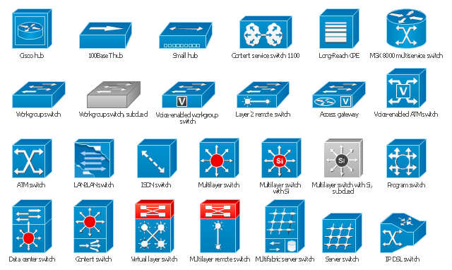
The vector stencils library "Cisco switches and hubs" contains 26 symbols for drawing computer network diagrams using the ConceptDraw PRO diagramming and vector drawing software.
"A network switch (sometimes known as a switching hub) is a computer networking device that is used to connect many devices together on a computer network. A switch is considered more advanced than a hub because a switch will only send a message to the device that needs or requests it, rather than broadcasting the same message out of each of its ports.
A switch is a multi-port network bridge that processes and forwards data at the data link layer (layer 2) of the OSI model. Some switches have additional features, including the ability to route packets. These switches are commonly known as layer-3 or multilayer switches. Switches exist for various types of networks including Fibre Channel, Asynchronous Transfer Mode, InfiniBand, Ethernet and others." [Network switch. Wikipedia]
"An Ethernet hub, active hub, network hub, repeater hub, multiport repeater or hub is a device for connecting multiple Ethernet devices together and making them act as a single network segment. It has multiple input/ output (I/ O) ports, in which a signal introduced at the input of any port appears at the output of every port except the original incoming. A hub works at the physical layer (layer 1) of the OSI model. The device is a form of multiport repeater. Repeater hubs also participate in collision detection, forwarding a jam signal to all ports if it detects a collision.
Some hubs may also come with a BNC and/ or Attachment Unit Interface (AUI) connector to allow connection to legacy 10BASE2 or 10BASE5 network segments." [Ethernet hub. Wikipedia]
The example "Design elements - Cisco switches and hubs" is included in the Cisco Network Diagrams solution from the Computer and Networks area of ConceptDraw Solution Park.
Cisco switches and hubs symbols
The vector stencils library "VHF UHF SHF" contains 52 symbols for VHF, UHF, and SHF circuit design, including capacitance measurers, nonreciprocal devices, modulators, phase shifters, field polarization devices, and filters.
"Very high frequency (VHF) is the ITU-designated range of radio frequency electromagnetic waves from 30 MHz to 300 MHz, with corresponding wavelengths of one to ten meters. Frequencies immediately below VHF are denoted high frequency (HF), and the next higher frequencies are known as ultra high frequency (UHF).
Common uses for VHF are FM radio broadcasting, television broadcasting, land mobile stations (emergency, business, private use and military), long range data communication up to several tens of kilometres with radio modems, amateur radio, and marine communications. Air traffic control communications and air navigation systems (e.g. VOR, DME & ILS) work at distances of 100 kilometres or more to aircraft at cruising altitude.
VHF was previously used for analog television stations in the US." [Very high frequency. Wikipedia]
"Ultra-high frequency (UHF) designates the ITU radio frequency range of electromagnetic waves between 300 MHz and 3 GHz (3,000 MHz), also known as the decimetre band or decimetre wave as the wavelengths range from one to ten decimetres; that is 1 decimetre to 1 metre. Radio waves with frequencies above the UHF band fall into the SHF (super-high frequency) or microwave frequency range. Lower frequency signals fall into the VHF (very high frequency) or lower bands. UHF radio waves propagate mainly by line of sight; they are blocked by hills and large buildings although the transmission through building walls is high enough for indoor reception. They are used for television broadcasting (digital and analogue), cordless phones, walkie-talkies, satellite communication, and numerous other applications.
The IEEE defines the UHF radar band as frequencies between 300 MHz and 1 GHz. Two other IEEE radar band overlap the ITU UHF band: the L band between 1 and 2 GHz and the S band between 2 and 4 GHz." [Ultra high frequency. Wikipedia]
"Super high frequency (or SHF) is the ITU designation for radio frequencies (RF) in the range of 3 GHz and 30 GHz. This band of frequencies is also known as the centimetre band or centimetre wave as the wavelengths range from ten to one centimetres. These frequencies fall within the microwave band, so radio waves with these frequencies are called microwaves. The small wavelength of microwaves allows them to be directed in narrow beams by aperture antennas such as parabolic dishes, so they are used for point-to-point communication and data links, and for radar. This frequency range is used for most radar transmitters, microwave ovens, wireless LANs, cell phones, satellite communication, microwave radio relay links, and numerous short range terrestrial data links. The commencing wireless USB technology will be using approximately 1/ 3 of this spectrum.
Frequencies in the SHF range are often referred to by their IEEE radar band designations: S, C, X, Ku, K, or Ka band, or by similar NATO or EU designations." [Super high frequency. Wikipedia]
The shapes example "Design elements - VHF UHF SHF" was drawn using the ConceptDraw PRO diagramming and vector drawing software extended with the Electrical Engineering solution from the Engineering area of ConceptDraw Solution Park.
VHF, UHF, SHF symbols

The vector stencils library "Video and audio" contains 50 symbols of devices and equipment.
Use it for drawing audio and video system layouts, cabling floor plans, electrical circuit schematic and wiring diagrams in the ConceptDraw PRO diagramming and vector drawing software.
The vector stencils library "Video and audio" is included in the Electric and Telecom Plans solution from the Building Plans area of ConceptDraw Solution Park.
Audio amplifier

RF amplifier

Video amplifier

Generic automatic switcher

Generic A/V switcher

Generic source component

System components

Headphone jack

Infrared receiver

Infrared transmitter

Music keypad

Mono speaker outlet

Stereo speaker outlet

Speaker ceiling

Speaker in-wall

Speaker subwoofer

Speaker weatherproof

Buzzer and bleeper

Piezo transducer

Microphone

Earphone

Cable antenna outlet

Master antenna outlet

Volume control

Volume control

Flush mounted intercom unit

Master intercom and directory unit

Floor mounted microphone outlet

Wall mounted microphone outlet

Ceiling mounted speaker

Speaker horn

Wall mounted speaker

Call in switch

Ceiling mounted paging speaker

Wall mounted paging speaker

Flush mounted data floor outlet

Flush mounted data floor outlet

Flush mounted data / telephone floor outlet

Surface mounted data floor outlet

Surface mounted data floor outlet

Surface mounted data / telephone floor outlet

Data outlet

Telephone outlet

Telephone, data outlet

Wall mounted telephone outlet

Equipment cabinet

Free standing equipment rack

Plywood backboard

Terminal cabinet with plywood backing

Wall mounted equipment rack

The vector stencils library "Data flow diagram (DFD)" contains 15 DFD elements.
Use it for process-oriented models, data-oriented models, data flowcharts, data process diagrams, structured analysis diagrams, and information flow diagrams in the ConceptDraw PRO diagramming and vector drawing software extended with the Data Flow Diagrams solution from the Software Development area of ConceptDraw Solution Park.
Use it for process-oriented models, data-oriented models, data flowcharts, data process diagrams, structured analysis diagrams, and information flow diagrams in the ConceptDraw PRO diagramming and vector drawing software extended with the Data Flow Diagrams solution from the Software Development area of ConceptDraw Solution Park.
State (Multi State)
-data-flow-diagram-(dfd)---vector-stencils-library.png--diagram-flowchart-example.png)
State (Multi State)
-data-flow-diagram-(dfd)---vector-stencils-library.png--diagram-flowchart-example.png)
State (Multi State)
-data-flow-diagram-(dfd)---vector-stencils-library.png--diagram-flowchart-example.png)
Stop state 2
---vector-stencils-library.png--diagram-flowchart-example.png)
External Interactor
---vector-stencils-library.png--diagram-flowchart-example.png)
Entity Relationship
---vector-stencils-library.png--diagram-flowchart-example.png)
Oval process
---vector-stencils-library.png--diagram-flowchart-example.png)
Object
---vector-stencils-library.png--diagram-flowchart-example.png)
Entity
---vector-stencils-library.png--diagram-flowchart-example.png)
Entity (Rounded Corners)
-data-flow-diagram-(dfd)---vector-stencils-library.png--diagram-flowchart-example.png)
Entity with ID and Location Mention(Rounded Corners)
-data-flow-diagram-(dfd)---vector-stencils-library.png--diagram-flowchart-example.png)
Data store 1
---vector-stencils-library.png--diagram-flowchart-example.png)
Data store 2
---vector-stencils-library.png--diagram-flowchart-example.png)
Data store 3
---vector-stencils-library.png--diagram-flowchart-example.png)
Data store (with ID)
-data-flow-diagram-(dfd)---vector-stencils-library.png--diagram-flowchart-example.png)
- Example of DFD for Online Store ( Data Flow Diagram) | Simbol ...
- Business Report Pie. Pie Chart Examples | Scatter Graph Charting ...
- Data Flow Diagram Examples | Structured Systems Analysis and ...
- Data Flow Diagram Symbols. DFD Library | UML Flowchart Symbols ...
- UML Class Diagram Notation | Entity Relationship Diagram Symbols ...
- Mechanical Drawing Symbols | Gane Sarson Diagram | Electrical ...
- Simbol Drawing Engineering
- Engineering Graphics Simbol
- Simbol Flowchart Visual Basic
- Valve Simbol Pic
- ATM Network. Computer and Network Examples | Network ...
- Entity Relationship Diagram Symbols | ERD Symbols and Meanings ...
- Er Diagram Attributes Simbol
- Mechanical Drawing Symbols | Electrical Symbols — Terminals and ...
- Basic Flowchart Symbols and Meaning | Types of Flowcharts ...
- Design elements - ERD (crow's foot notation) | Cloud Computing ...
- Drwang Simbol
- Flowchart design. Flowchart symbols, shapes, stencils and icons ...
- Drawing Engg Basic Simbol
- Data - Vector stencils library | Design elements - Data BPMN 2.0 ...