Bubble Chart
Creating different diagrams, flowcharts, schemes and charts, including the bubble charts created with the help of ConceptDraw DIAGRAM charting and drawing software is an inalienable part of being involved in any of so many different fields of business activity in order to do your business in a right way succeeding in what you do.
The mentioned drawings can always be used for presentations, everyday business meetings, conferences and many other occasions. It is always better to show what exactly you try to explain in the way of making such drawings, as charts, because they are one of the best ways to explain the information you have to the other people, especially if you have lots of complex data which includes lots of numbers.
The mentioned kind of drawing can be used in many different kinds of business. Making bubble charts is never as difficult as long as you have ConceptDraw DIAGRAM software — a professional as well as the convenient bubble chart maker, offering all the needed tools for simple and professional drawing. Having the smart looking charts, such as bubble charts created with the aid of ConceptDraw DIAGRAM is very important in case you want other people, such as your director, your colleagues, your clients or partners to understand what exactly you mean by putting so much information into one presentation.
Simplifying a large amount of data in a way of illustrating it with the help of such charts, as bubble ones, is always a good idea, because bubble charts are simple and easy to deal with as well as convenient to look through and to realise the connections between different pieces of information represented in a way of so-called “bubbles”. The mentioned “bubbles” are those which are used for representing the needed parts of the whole system, which needs to be illustrated, connected with each other the way it becomes obvious they all belong to the same describing lot of information.
In order to see the difference in numbers in a better way than in a way of text, as well as to separate some chaotic set of numbers so they are simpler to understand, it is always to structure the given data so it becomes more understandable. “Bubble chart” may be the best option for such reason as this kind of chart is very well known and commonly used especially for such reason: to simplify the understanding of some particular information, that may be more difficult to get in a way of a boring text.
Those IT specialists, who deal with such drawings every day making them look simply smart and professional, have developed a unique, very useful application — ConceptDraw DIAGRAM vector diagramming and drawing one, especially for a purpose of simplifying your work with making your own charts using the pre-made tools, such as the previously created graphical objects, as “bubbles”. Having the needed bits and pieces so wanted for making your own graphs and charts, you can simply put them all together on one drawing and so to charge their places anytime you want as well as their colours.
Using bubble charts becomes more and more popular nowadays, especially it is relevant for making presentations or some other business documentation, including the needed illustrations for simplifying understanding the data. Bubble charts are used in very many spheres of different kinds of business being very useful as well as convenient to both draw and use for figuring out the connections between different pieces of information.
With the help of this kind of chart you can always illustrate at least three different dimensions of some particular data. Each of the existing entities has its triplet of the associated data, plotted in a way of a disk, expressing two of the values of the very first entity going through the “xy” disk's location. The third, though, goes through its size. Using bubble charts can simply facilitate the understanding of some medical, economical, social as well as any other scientific relationships to make it easier to get involved in the project for your partners, co-workers, employees, clients and other.
Basically, within each bubble chart, the data points are presented in a way of bubbles making it obvious to understand the difference between the different entities or elements by looking at their value and size. The number of such data points can always vary allowing you to put as many as needed depending on how many different numbers you want to mention. Thus, the more “bubble” with the entities you use, the bigger your chart is.
As well as the quantity of the “bubbles”, the sizes of them can vary, determined by the values in the third data series. Trying to make such kind of chart for the first time from a scratch can be a challenge. So why not to simplify your work by using the already previously created examples of such chart having the needed solution downloaded from ConceptDraw STORE application — another product of CS Odessa, developed for a reason of helping all the ConceptDraw DIAGRAM users make their professionally looking charts within only a few minutes.
Example 1. Bubble Chart - Page Rank
Having Business Diagrams Solution means having all the necessary tools for making your drawings of the bubble charts, as it offers the extensive drawing tools, included in a Bubble Diagrams Library. The mentioned library consists of 28 vector shapes, such as Simple Bubble, Simple Small Bubble, Light Blue Bubble, Light Red Bubble, Light Bubble Strong Big Bubble, Strong Bubble, Strong Small Bubble, Light Grey Big Bubble, Light Grey Bubble, Simple Big Bubble, Light Grey Small Bubble, Grey Big Bubble, Grey Bubble, Grey Small Bubble, Red Bubble, Orange Bubble, Yellow Bubble, Green Bubble, Blue Bubble, Violet Bubble, Light Orange Bubble, Light Yellow Bubble, Light Green Bubble, Light Blue Bubble, Light Small Bubble, and other. Any of the mentioned design elements can be used for drawing Bubble Charts of any complexity within a very short period of time as long as you have ConceptDraw DIAGRAM and the described solution.

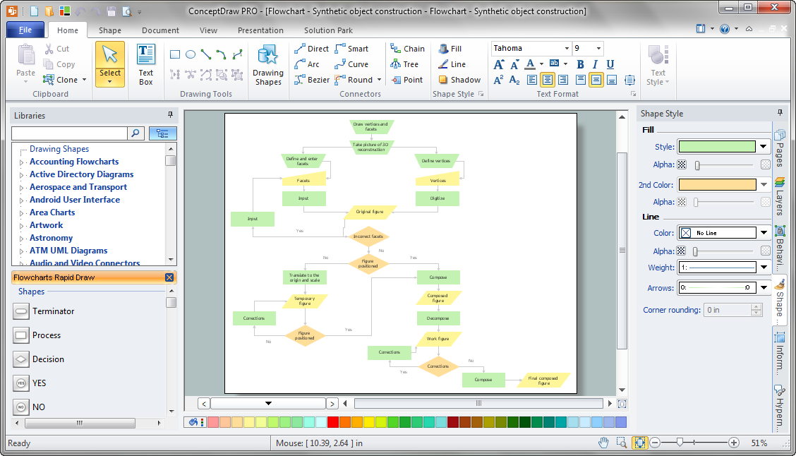
Example 2. Business Diagrams Solution in ConceptDraw STORE
Bubble Chart is a visual way to illustrate the data. The use of colors is effective for the Bubble Chart. First of all colors make it interesting and successful, you can visualize additionally the levels by different colors, or change the color intensity with the increasing (decreasing) the distance from the main idea. You can also variate by bubble sizes.

Example 3. Bubble Chart — Employee Needs
This Bubble Chart was created in ConceptDraw DIAGRAM using the tools of Business Diagrams Solution. It visually shows the structure of employee needs, the importance of needs is indicated by sizes and colors of bubbles. An experienced user spent 15 minutes creating this sample.
Use the Business Diagrams Solution for ConceptDraw DIAGRAM software for quick, easy, and effective design your own Bubble Chart.
All source documents are vector graphic documents. They are available for reviewing, modifying, or converting to a variety of formats (PDF file, MS PowerPoint, MS Visio, and many other graphic formats) from the ConceptDraw STORE. The Business Diagrams Solution is available for all ConceptDraw DIAGRAM or later users.