Mechanical Drawing Symbols

Electrical Symbols, Electrical Diagram Symbols

Electrical Symbols — Terminals and Connectors

Accounting Flowchart Symbols

Entity Relationship Diagram Symbols

This engineering drawing present weld type symbols and fillet weld symbols.
The weld type symbol is typically placed above or below the center of the reference line, depending on which side of the joint it's on. The symbol is interpreted as a simplified cross-section of the weld.
"Fillet welding refers to the process of joining two pieces of metal together whether they be perpendicular or at an angle. These welds are commonly referred to as Tee joints which are two pieces of metal perpendicular to each other or Lap joints which are two pieces of metal that overlap and are welded at the edges. The weld is aesthetically triangular in shape and may have a concave, flat or convex surface depending on the welder’s technique. Welders use fillet welds when connecting flanges to pipes, welding cross sections of infrastructure, and when fastening metal by bolts isn't strong enough." [Fillet weld. Wikipedia]
The engineering drawing example Welding symbols is included in the Mechanical Engineering solution from Engineering area of ConceptDraw Solution Park.
Welding joint symbols

Gane Sarson Diagram

IDEF0 Flowchart Symbols

ERD Symbols and Meanings


Swim Lane Flowchart Symbols

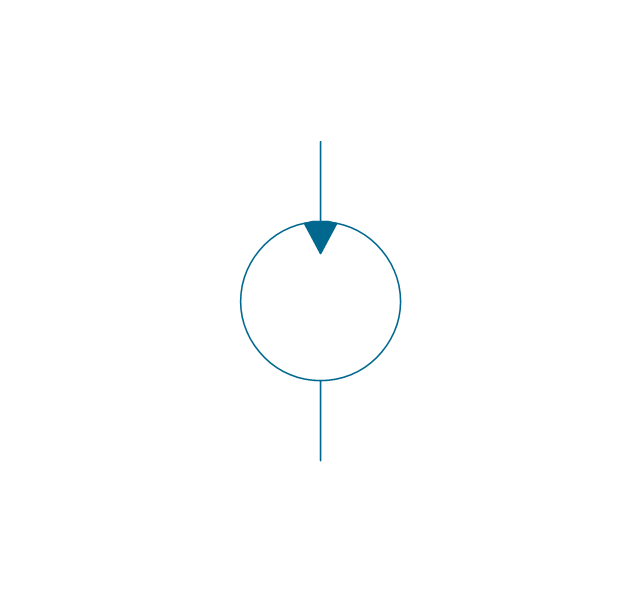
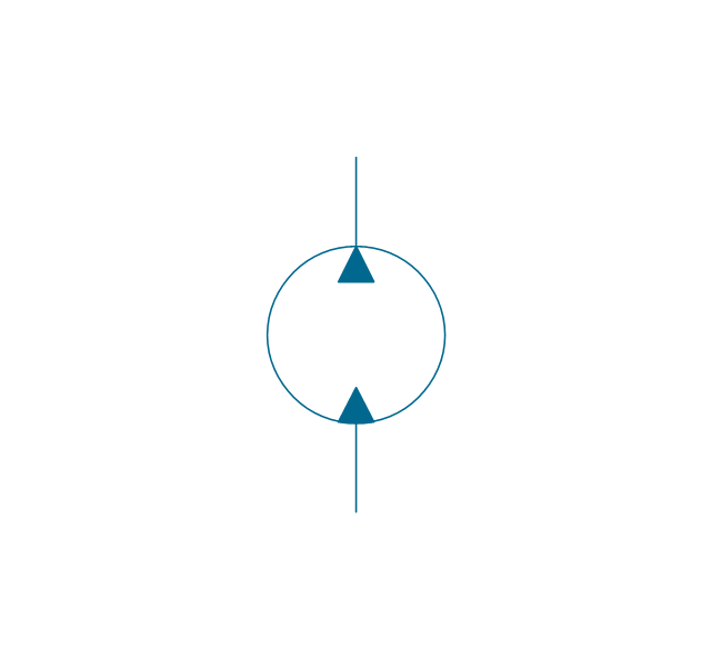
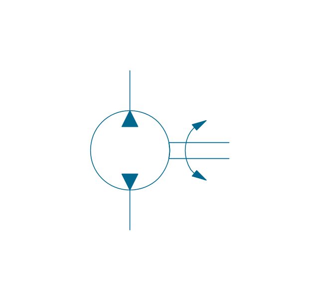
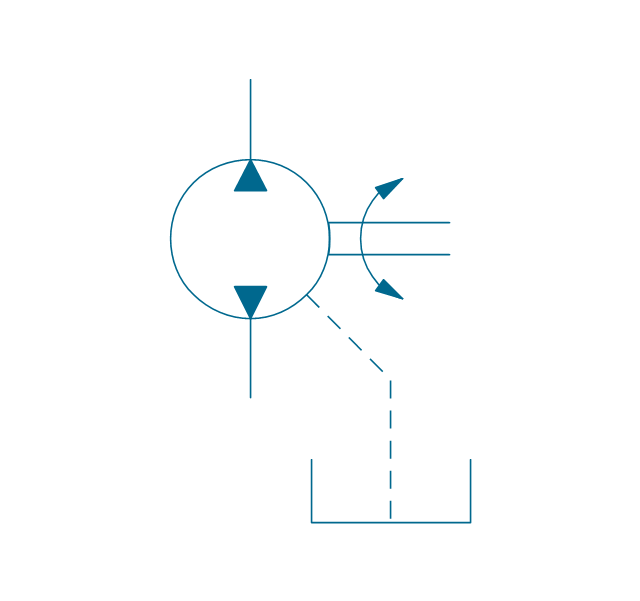
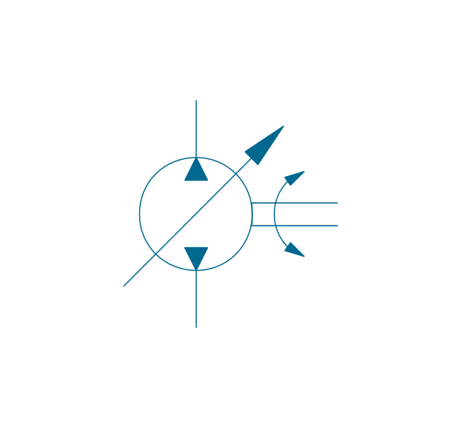
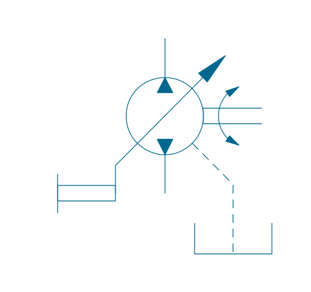
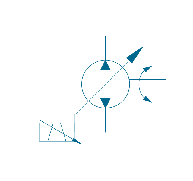
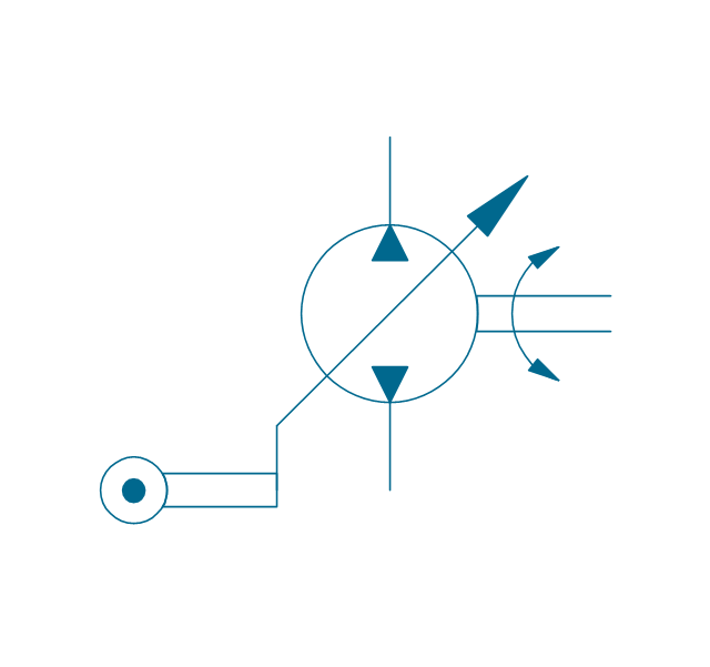
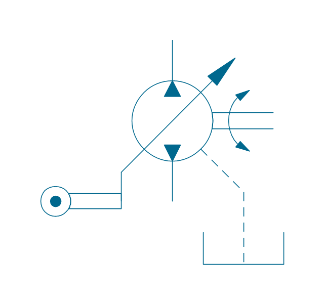
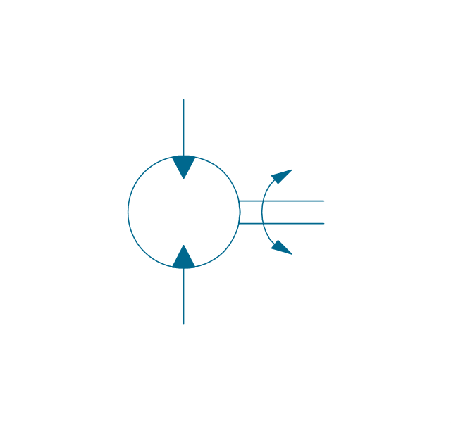
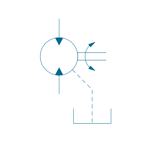
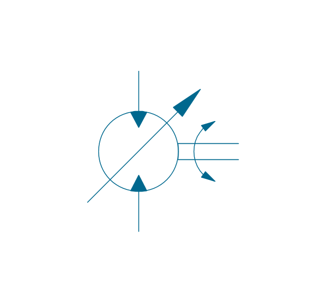
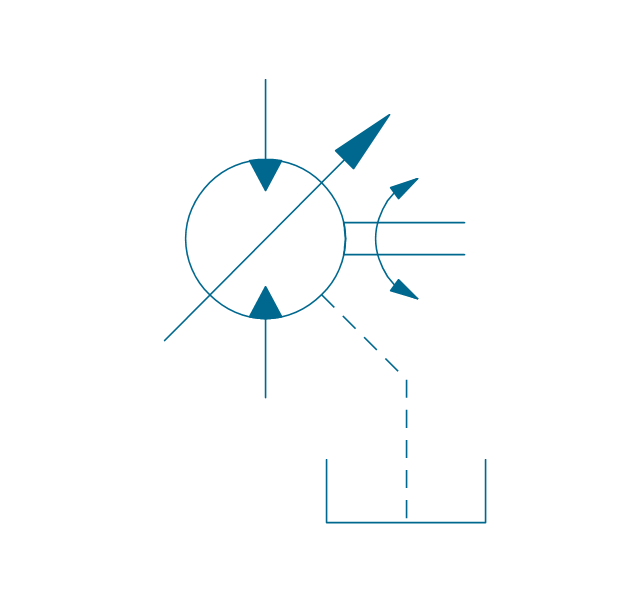
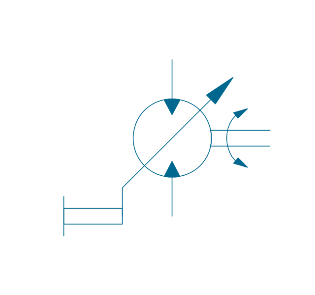
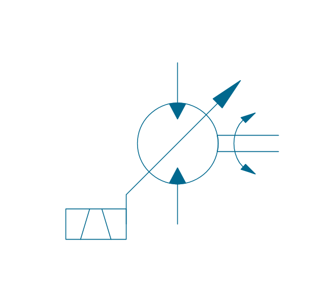
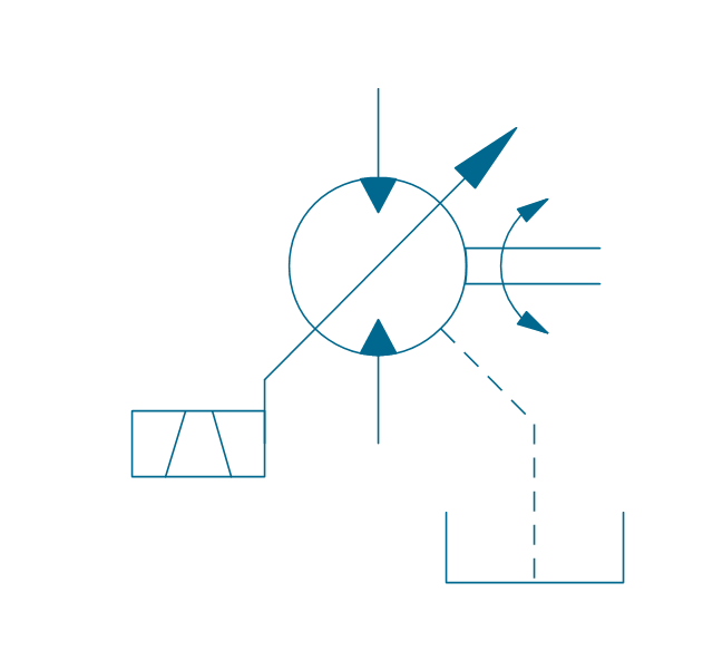
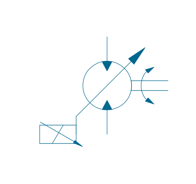
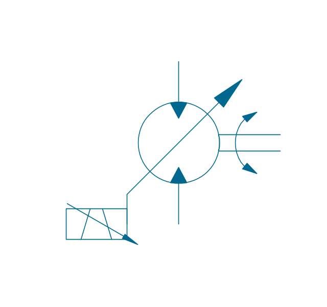
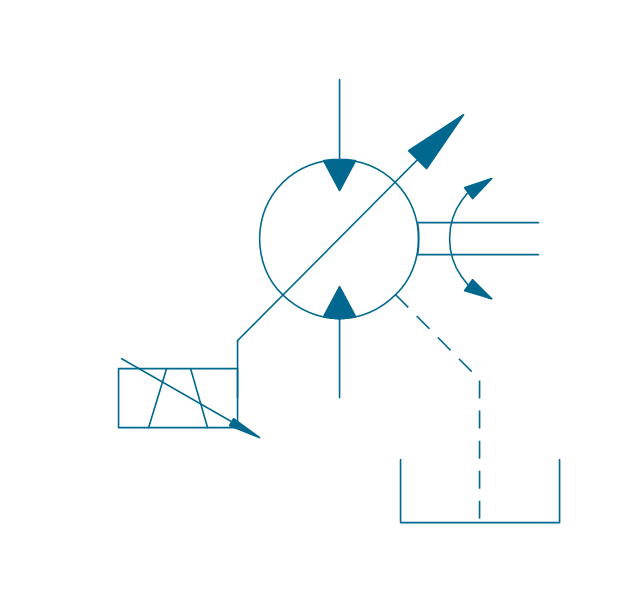
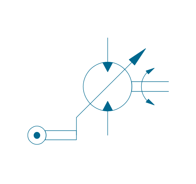
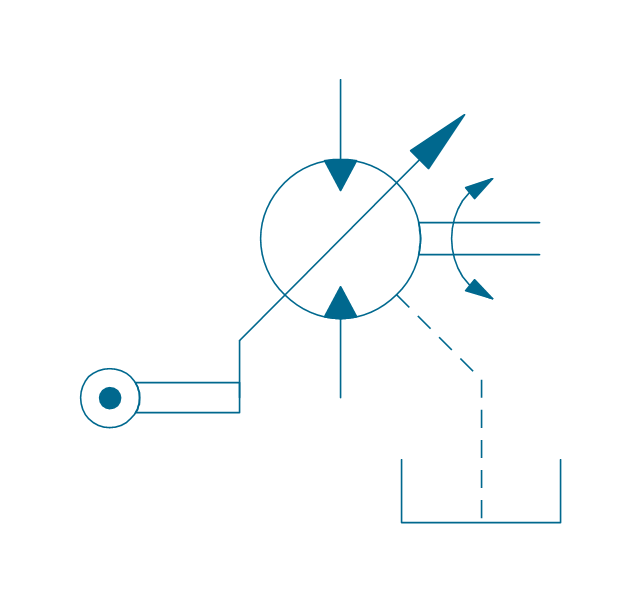
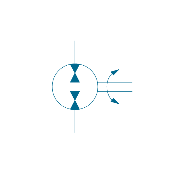
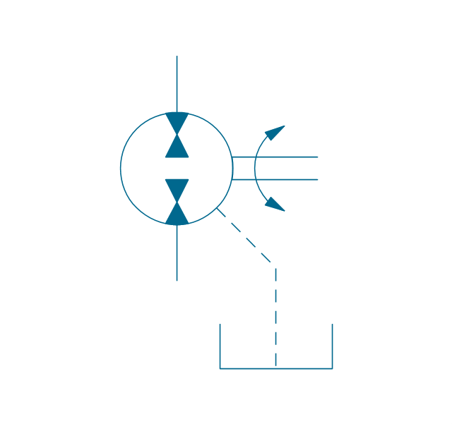
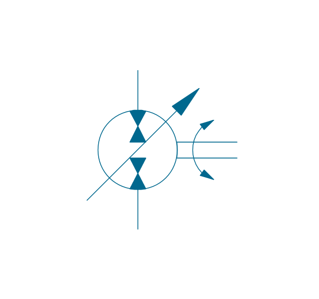
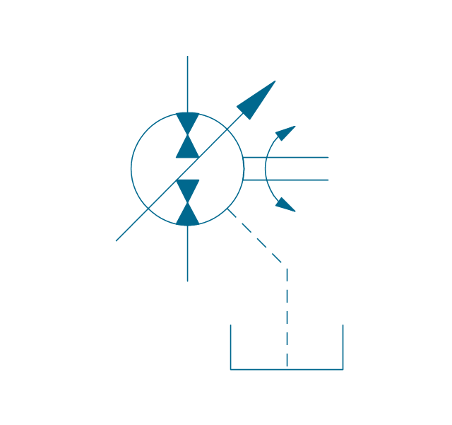
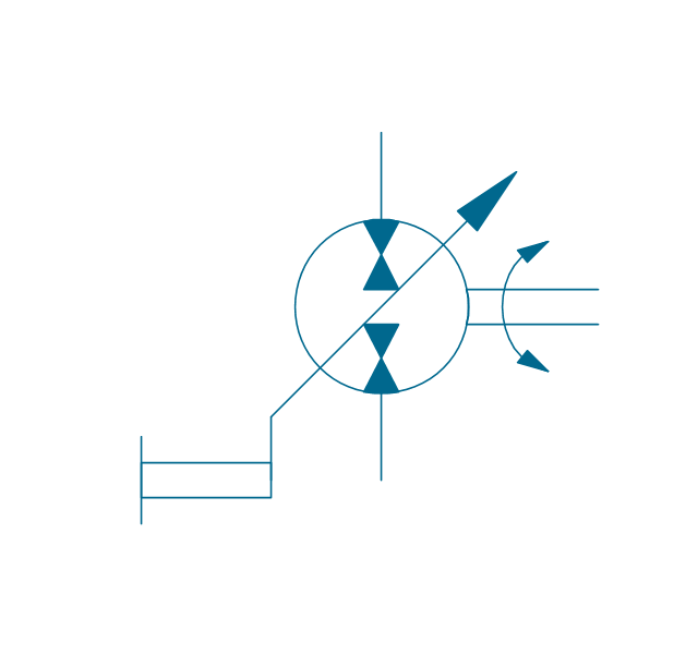
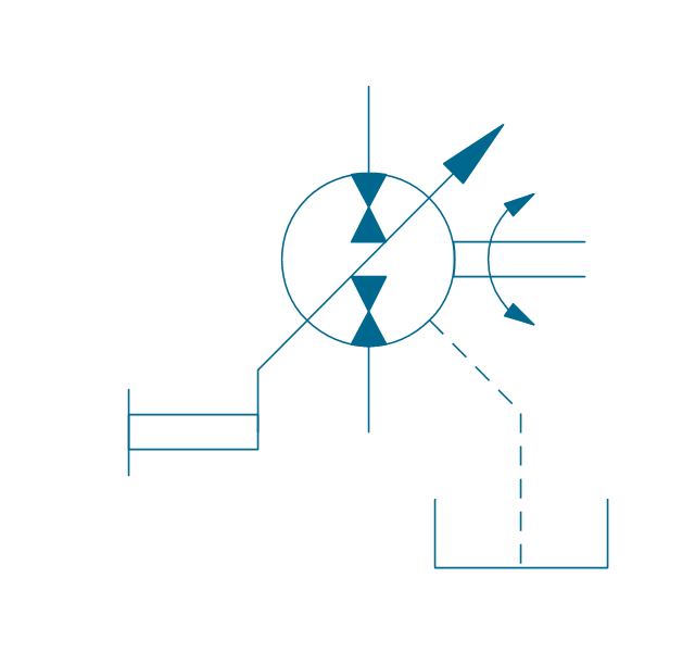
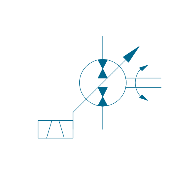
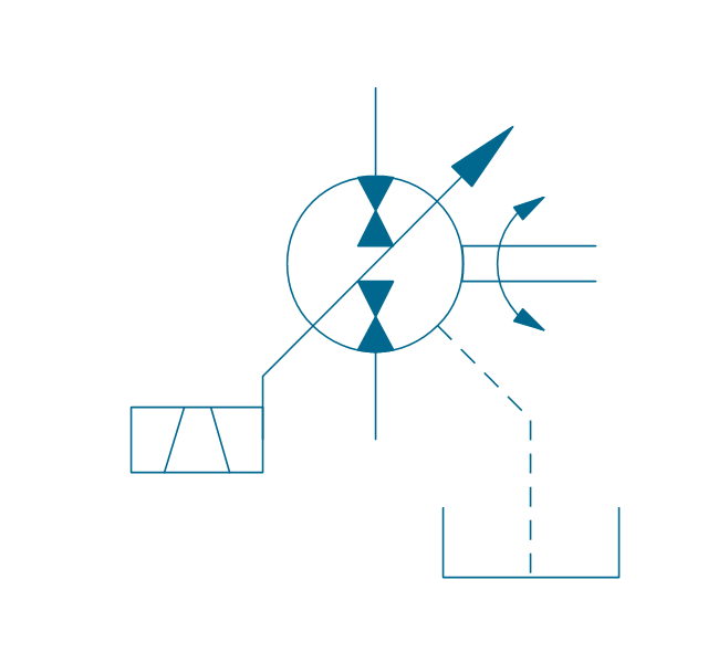
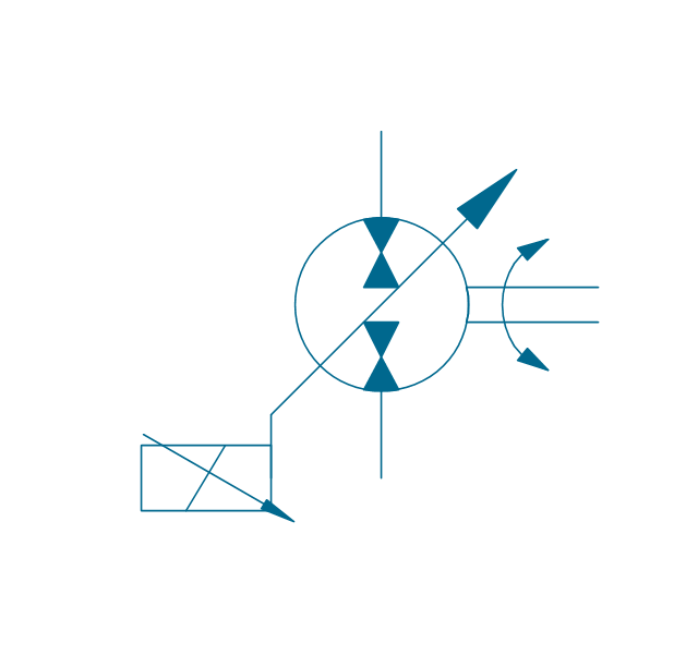
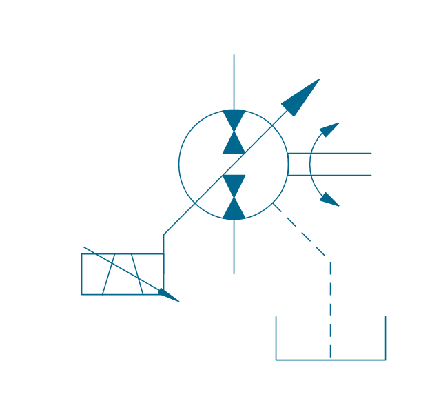
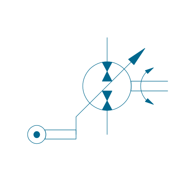
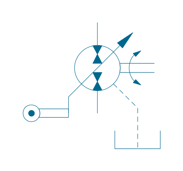
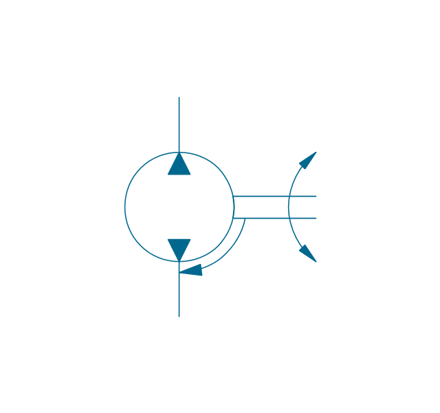
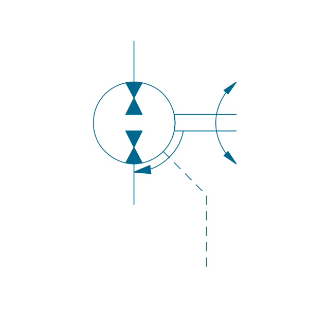
"Directional control valves are one of the most fundamental parts in hydraulic machinery as well and pneumatic machinery. They allow fluid flow into different paths from one or more sources. They usually consist of a spool inside a cylinder which is mechanically or electrically controlled. The movement of the spool restricts or permits the flow, thus it controls the fluid flow. ...
While working with layouts of hydraulic machinery it is cumbersome to draw actual picture of every valve and other components.instead of pictures symbols are used for variety of components in the hydraulic system to highlight the functional aspects. symbol for directional control valve is made of number of square boxes adjacent to each other depending on the number of positions.connections to the valve are shown on these squares by capital letters.usually they are named only in their normal position and not repeated in other positions.actuation system of the valve is also designated in its symbol." [Directional control valve. Wikipedia]
The Mac template "Pneumatic 5-ported 3-position valve" for the ConceptDraw PRO diagramming and vector drawing software is included in the Mechanical Engineering solution from the Engineering area of ConceptDraw Solution Park.
www.conceptdraw.com/ solution-park/ engineering-mechanical
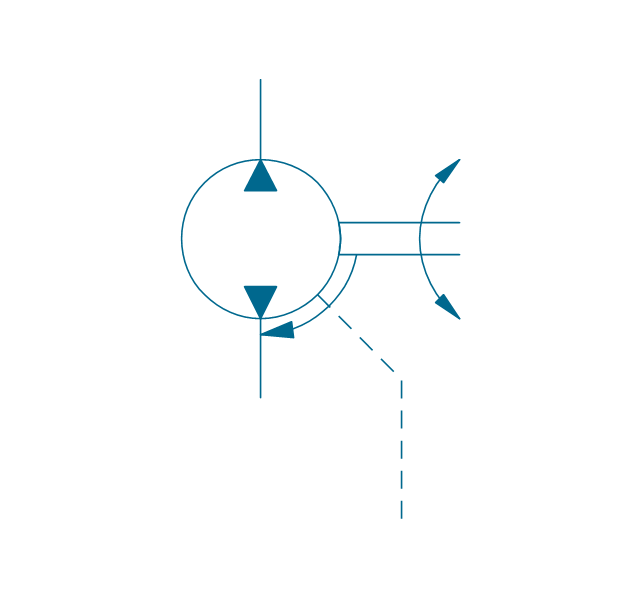
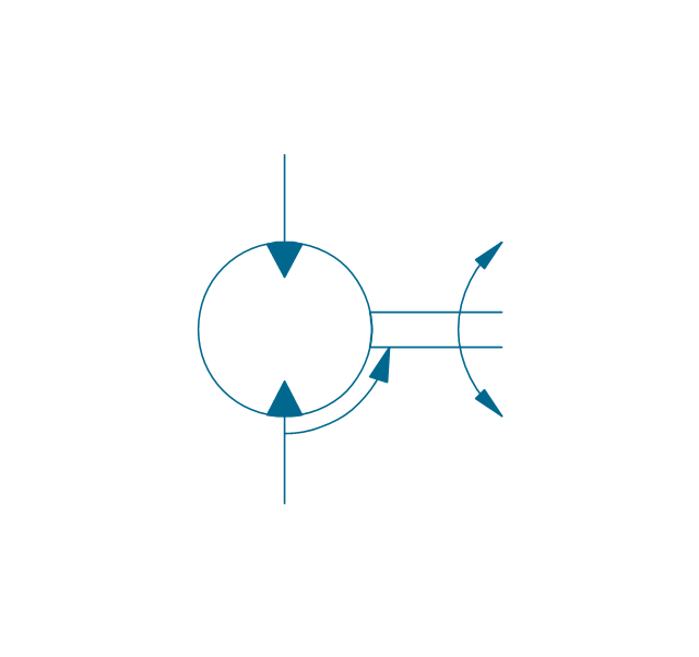
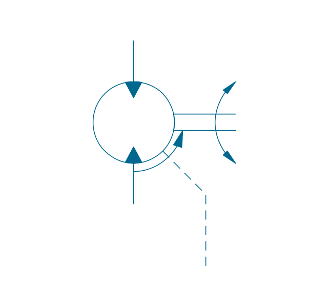
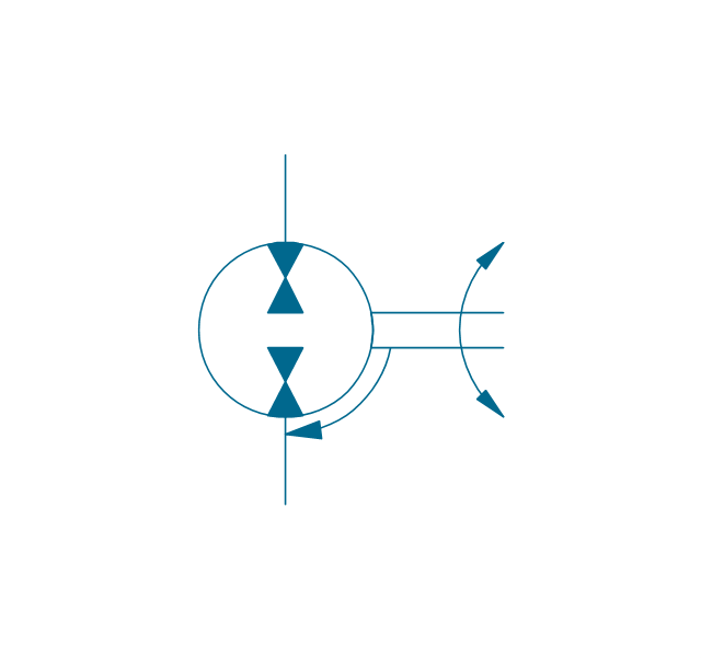
Pneumatic directional control valve

Beauty in nature Illustrations and Clipart

The vector stencils library "Fluid power equipment" contains 113 symbols of hydraulic and pneumatic equipment including pumps, motors, air compressors, cylinders, meters, gauges, and actuators.
Use it to design fluid power and hydraulic control systems in the ConceptDraw PRO diagramming and vector drawing software extended with the Mechanical Engineering solution from the Engineering area of ConceptDraw Solution Park.
www.conceptdraw.com/ solution-park/ engineering-mechanical
Use it to design fluid power and hydraulic control systems in the ConceptDraw PRO diagramming and vector drawing software extended with the Mechanical Engineering solution from the Engineering area of ConceptDraw Solution Park.
www.conceptdraw.com/ solution-park/ engineering-mechanical
Actuator (semi-rotary), pneumatic
,-pneumatic-fluid-power-equipment---vector-stencils-library.png--diagram-flowchart-example.png)
Actuator (semi-rotary), hydraulic
,-hydraulic-fluid-power-equipment---vector-stencils-library.png--diagram-flowchart-example.png)
Drive unit, pneumatic

Drive unit, hydraulic

Sgl-act. cylinder, pneum., left spring

Sgl-act. cylinder, pneum., right spring

Sgl-act. cylinder, pneumatic

Sgl-act. cylinder, hydr., left spring

Sgl-act. cylinder, hydr., right spring

Sgl-act. cylinder, hydraulic

Dbl-act. cylinder, pneumatic

Dbl-act. cylinder, pneum., sgl cushion

Dbl-act. cylinder, pneum., dbl cushion

Dbl-act. cylinder, pneum., adjustable

Dbl-act. cylinder, pneum., sgl cushion, adj.

Dbl-act. cylinder, pneum., dbl cushion, adj.

Dbl-act. cylinder, hydraulic

Dbl-act. cylinder, hydr., sgl cushion

Dbl-act. cylinder, hydr., dbl cushion

Dbl-act. cylinder, hydr., adjustable

Dbl-act. cylinder, hydr., sgl cushion, adj.

Dbl-act. cylinder, hydr., dbl cushion, adj.

Dbl-act. cylinder, magnetic

Dbl-act. cylinder, magn., sgl cushion

Dbl-act. cylinder, magn., dbl cushion

Dbl-act. cylinder, magn., adjustable

Dbl-act. cylinder, magn., sgl cushion, adj.

Dbl-act. cylinder, magn., dbl cushion, adj.

Dbl-act. dbl-end. cylinder, pneumatic

Dbl-act. dbl-end. cylinder, pneum., sgl cushion

Dbl-act. dbl-end. cylinder, pneum., dbl cushion

Dbl-act. dbl-end. cylinder, pneum., adjustable

Dbl-act. dbl-end. cylinder, pneum., sgl cushion, adj.

Dbl-act. dbl-end. cylinder, pneum., dbl cushion, adj.

Dbl-act. dbl-end. cylinder, hydraulic

Dbl-act. dbl-end. cylinder, hydr., sgl cushion

Dbl-act. dbl-end. cylinder, hydr., dbl cushion

Dbl-act. dbl-end. cylinder, hydr., adjustable

Dbl-act. dbl-end. cylinder, hydr., sgl cushion, adj.

Dbl-act. dbl-end. cylinder, hydr., dbl cushion, adj.

Telescopic cylinder, pneum., dbl-act.

Telescopic cylinder, hydr., dbl-act.

Telescopic cylinder, pneum., sgl-act.

Telescopic cylinder, hydr., sgl-act.

Actuator, hydraulic-pneumatic

Actuator, pneumatic-hydraulic

Intensifier, pneumatic

Intensifier, hydraulic

Intensifier, hydraulic-pneumatic

Intensifier, pneumatic-hydraulic

Intensifier, pneumatic-hydraulic

Intensifier, hydraulic-pneumatic

Actuator, pneumatic-hydraulic

Actuator, hydraulic-pneumatic

Accumulator

Accumulator, gas loaded

Accumulator, spring loaded

Accumulator, auxiliary gas bottle

Air receiver

Energy source, pneumatic

Energy source, hydraulic

Energy source, electric motor

Energy source, non-electric prime mover

Vented reservoir

Sealed reservoir

Filter

Filter, magnetic element

Filter, contamination indicator

Automatic drain filter separator

Manual drain filter separator

Separator, automatic drain

Separator, manual drain

Air dryer

Lubricator

Air service unit, filter, separator

Air service unit, separator

Air service unit, filter

Air service unit

Liquid cooler

Gas cooler

Cooler

Liquid heater

Gas heater

Heater

Liquid temperature controller

Gas temperature controller

Temperature controller

Liquid temperature controller 2

Gas temperature controller 2

Temperature controller 2

Pressure indicator

Pressure gauge

Differential pressure gauge

Thermometer

Liquid level measuring instrument

Flow indicator

Flow meter

Integrating flow meter

Tachometer

Torque measurement equipment

Pressure switch

Limit switch

Transducer

Pulse counter

Pulse counter 2

Silencer

Drain (inlet below fluid, drain line)
-fluid-power-equipment---vector-stencils-library.png--diagram-flowchart-example.png)
Drain (inlet below fluid, return line)
-fluid-power-equipment---vector-stencils-library.png--diagram-flowchart-example.png)
Drain (inlet above fluid, drain line)
-fluid-power-equipment---vector-stencils-library.png--diagram-flowchart-example.png)
Drain (inlet above fluid, return line)
-fluid-power-equipment---vector-stencils-library.png--diagram-flowchart-example.png)
Oil tank

Oil tank, empty

Air compressor

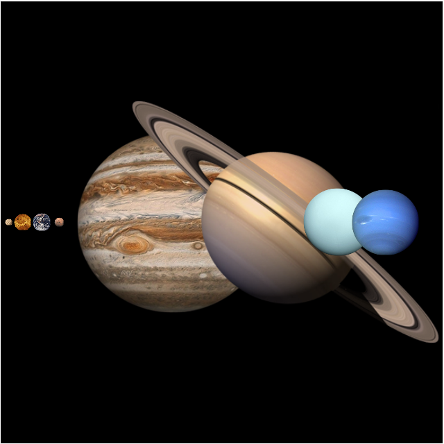
This vector stencils library contains 30 clipart images and astronomical symbols of sun and stars, solar system planets and moon.
Use these shapes for drawing your astronomical diagrams and illustrations.
Use these shapes for drawing your astronomical diagrams and illustrations.
Solar system
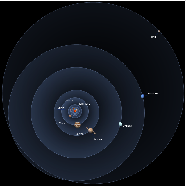
Sun

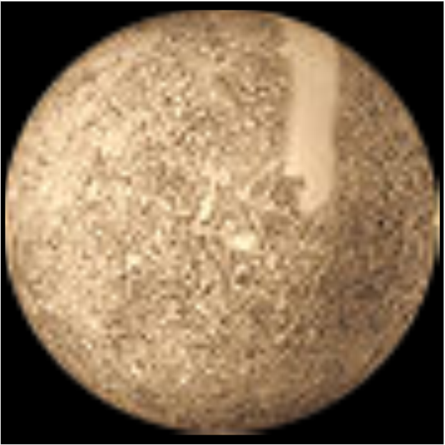
Mercury
Venus

Earth

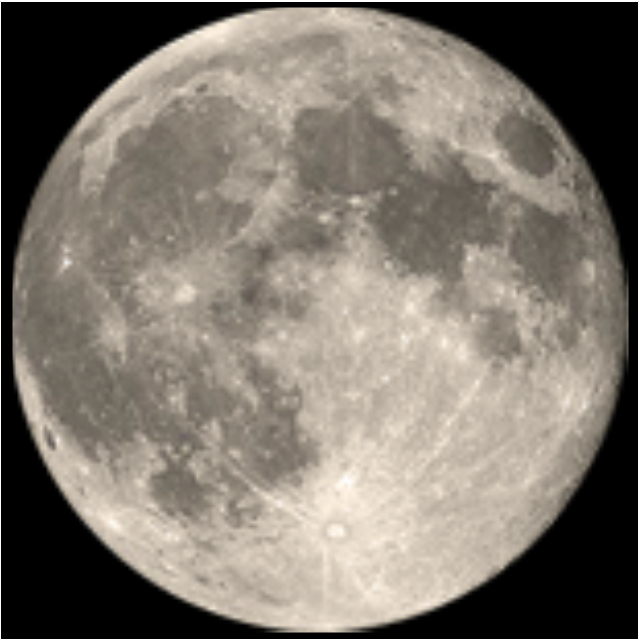
Moon
Mars

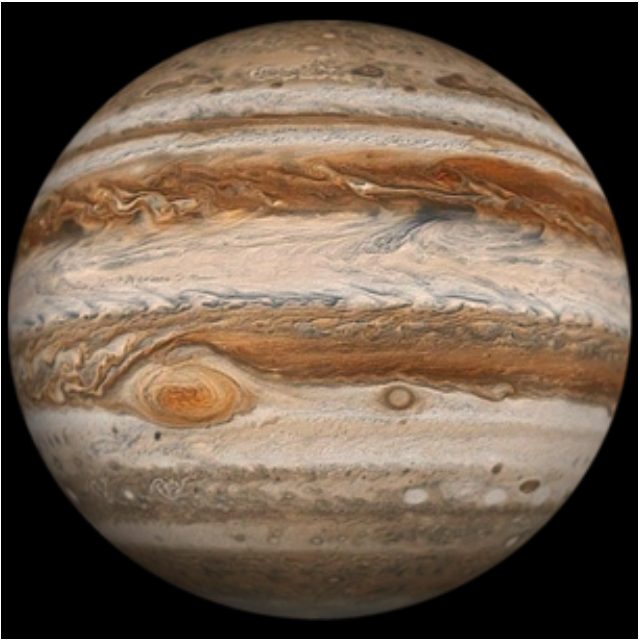
Jupiter
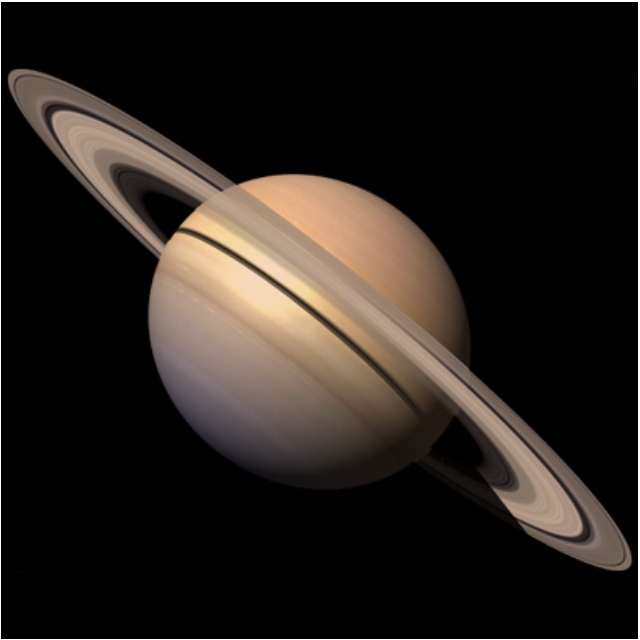
Saturn
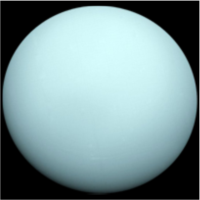
Uranus
Neptune

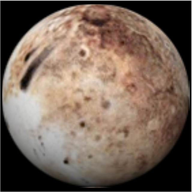
Pluto
Red giant

Yellow giant

Blue giant

Red dwarf

White dwarf

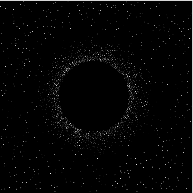
Black hole
Planets to scale
Sun symbol
Mercury symbol

Venus symbol

Earth symbol
Moon symbol

Mars symbol
Jupiter symbol

Saturn symbol
Neptune symbol

Uranus symbol
Pluto symbol

Interior Design

Bubble Chart
ERD Symbols and Meanings
Notation & Symbols for ERD

The vector stencils library "Hydraulic pumps and motors" contains 74 symbols of hydraulic equipment.
Use these shapes for engineering drawings of fluid power and hydraulic control systems in the ConceptDraw PRO diagramming and vector drawing software extended with the Mechanical Engineering solution from the Engineering area of ConceptDraw Solution Park.
www.conceptdraw.com/ solution-park/ engineering-mechanical
Pump, hydraulic

Motor, hydraulic
Pump-motor, hydraulic
Pump, fixed, external drain
Pump, fixed, external drain
Pump, variable
Pump, variable, external drain

Pump, var., manual override

Pump, var., manual override, drain
Pump, var., solenoid
Pump, var., solenoid, drain

Pump, var., solenoid 2

Pump, var., solenoid 2, drain
Pump, var., var. solenoid
Pump, var., var. solenoid, drain
Pump, var., var. solenoid 2
Pump, var., var. solenoid 2, drain

Pump, var., var., roller
Pump, var., roller, drain
Motor, fixed, external drain
Motor, fixed, external drain
Motor, variable
Motor, variable, external drain
Motor, var., manual override
Motor, var., manual override, drain

Motor, var., solenoid

Motor, var., solenoid, drain

Motor, var., solenoid 2
Motor, var., solenoid 2, drain
Motor, var., var. solenoid
Motor, var., var. solenoid, drain

Motor, var., var. solenoid 2
Motor, var., var. solenoid 2, drain
Motor, var., var., roller
Motor, var., roller, drain
Pump-motor, fixed, external drain
Pump-motor, fixed, external drain
Pump-motor, variable
Pump-motor, variable, external drain
Pump-motor, var., manual override
Pump-motor, var., manual override, drain
Pump-motor, var., solenoid

Pump-motor, var., solenoid, drain

Pump-motor, var., solenoid 2
Pump-motor, var., solenoid 2, drain
Pump-motor, var., var. solenoid
Pump-motor, var., var. solenoid, drain

Pump-motor, var., var. solenoid 2

Pump-motor, var., var. solenoid 2, drain
Pump-motor, var., var., roller
Pump-motor, var., roller, drain
Pump, fixed 2
Pump, fixed 2, drain
Pump, variable (sgl side)
-hydraulic-pumps-and-motors---vector-stencils-library.png--diagram-flowchart-example.png)
Pump, variable (sgl side), drain
,-drain-hydraulic-pumps-and-motors---vector-stencils-library.png--diagram-flowchart-example.png)
Pump, variable (dbl side)
-hydraulic-pumps-and-motors---vector-stencils-library.png--diagram-flowchart-example.png)
Pump, variable (dbl side), drain
,-drain-hydraulic-pumps-and-motors---vector-stencils-library.png--diagram-flowchart-example.png)
Motor, fixed 2
Motor, variable (sgl side)
-hydraulic-pumps-and-motors---vector-stencils-library.png--diagram-flowchart-example.png)
Motor, variable (dbl side)
-hydraulic-pumps-and-motors---vector-stencils-library.png--diagram-flowchart-example.png)
Motor, fixed 2, drain
Motor, variable (sgl side), drain
,-drain-hydraulic-pumps-and-motors---vector-stencils-library.png--diagram-flowchart-example.png)
Motor, variable (dbl side), drain
,-drain-hydraulic-pumps-and-motors---vector-stencils-library.png--diagram-flowchart-example.png)
Pump-motor, fixed 2
Pump-motor, fixed 2, drain
Pump-motor, variable (sgl side)
-hydraulic-pumps-and-motors---vector-stencils-library.png--diagram-flowchart-example.png)
Pump-motor, variable (sgl side), drain
,-drain-hydraulic-pumps-and-motors---vector-stencils-library.png--diagram-flowchart-example.png)
Pump-motor, variable (dbl side)
-hydraulic-pumps-and-motors---vector-stencils-library.png--diagram-flowchart-example.png)
Pump-motor, variable (dbl side), drain
,-drain-hydraulic-pumps-and-motors---vector-stencils-library.png--diagram-flowchart-example.png)
Pump, variable displacement
Motor, variable displacement
Pump-motor, variable displacement
Floating motor
Pressure compensator
How To use Appliances Symbols for Building Plan

- Mechanical Drawing Symbols | Design elements - Bearings ...
- Mechanical Engineering | Elements location of a welding symbol ...
- Simbol Mechanical
- Mechanical Drawing Symbols | Process Flow Diagram Symbols ...
- Drawing Engg Basic Simbol
- Mechanical Drawing Symbols | Electrical Symbols — Terminals and ...
- Mechanical Drawing Symbols | Design elements - Bearings ...
- Process Flow Diagram Symbols | Chemical Engineering | Chemical ...
- Simbol Adjustable Circuit Breaker
- Diagram Of Engineering Graphics
- Design elements - Pipes (part 1) | Welding symbols | Pipes 2 ...
- Electrical Symbols, Electrical Diagram Symbols | Mechanical ...
- Mechanical Drawing Symbols | ERD Symbols and Meanings ...
- Process Flow Diagram Symbols | Design elements - Heating ...
- Mechanical Drawing Symbols | Mechanical Engineering ...
- Electrical Drawing Software and Electrical Symbols | Building ...
- MOSFET | Engineering Drawing Iti Electrician All Simboll
- Electrical Symbols, Electrical Diagram Symbols | Electrical Symbols ...
- Simbol Simbol Drawing Wiring Harness
- Electrical Symbols, Electrical Diagram Symbols | Electrical Symbols ...