This VANET diagram example was drawn on the base of picture from the webpage "Security and Privacy in Location-based MANETs/ VANETs" from the Donald Bren School of Information and Computer Sciences, the University of California, Irvine. [ics.uci.edu/ ~keldefra/ manet.htm]
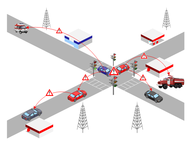
"A vehicular ad hoc network (VANET) uses cars as mobile nodes in a MANET to create a mobile network. A VANET turns every participating car into a wireless router or node, allowing cars approximately 100 to 300 metres of each other to connect and, in turn, create a network with a wide range. As cars fall out of the signal range and drop out of the network, other cars can join in, connecting vehicles to one another so that a mobile Internet is created. It is estimated that the first systems that will integrate this technology are police and fire vehicles to communicate with each other for safety purposes. Automotive companies like General Motors, Toyota, Nissan, DaimlerChrysler, BMW and Ford promote this term." [Vehicular ad hoc network. Wikipedia]
The VANET diagram example "Vehicular ad-hoc network" was created using the ConceptDraw PRO diagramming and vector drawing software extended with the Vehicular Networking solution from the Computer and Networks area of ConceptDraw Solution Park.
VANET diagram
 Vehicular Networking
The Vehicular Networking solution extends the ConceptDraw DIAGRAM software functionality with specialized tools, wide variety of pre-made vector objects, collection of samples and templates in order to help network engineers design vehicular network diagrams for effective network engineering activity, visualize vehicular networks, develop smart transportation systems, design various types of vehicle network management diagrams, regional network diagrams, vehicular communication system diagrams, vehicular ad-hoc networks, vehicular delay-tolerant networks, and other network engineering schemes.
Wireless Network LAN
Mesh Network Topology Diagram

Wireless Network Topology

Network Topologies


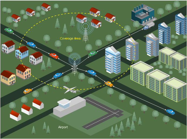
This diagram sample illustrates the cooperative vehicular delay-tolerant network operation.
"Delay-tolerant networking (DTN) is an approach to computer network architecture that seeks to address the technical issues in heterogeneous networks that may lack continuous network connectivity. Examples of such networks are those operating in mobile or extreme terrestrial environments, or planned networks in space.
Recently, the term disruption-tolerant networking has gained currency in the United States due to support from DARPA, which has funded many DTN projects. Disruption may occur because of the limits of wireless radio range, sparsity of mobile nodes, energy resources, attack, and noise." [Delay-tolerant networking. Wikipedia]
"Routing in delay-tolerant networking concerns itself with the ability to transport, or route, data from a source to a destination, which is a fundamental ability all communication networks must have. Delay- and disruption-tolerant networks (DTNs) are characterized by their lack of connectivity, resulting in a lack of instantaneous end-to-end paths. In these challenging environments, popular ad hoc routing protocols such as AODV and DSR fail to establish routes. This is due to these protocols trying to first establish a complete route and then, after the route has been established, forward the actual data. However, when instantaneous end-to-end paths are difficult or impossible to establish, routing protocols must take to a "store and forward" approach, where data is incrementally moved and stored throughout the network in hopes that it will eventually reach its destination. A common technique used to maximize the probability of a message being successfully transferred is to replicate many copies of the message in hopes that one will succeed in reaching its destination." [Routing in delay-tolerant networking. Wikipedia]
The example "Cooperative vehicular delay-tolerant network diagram" was created using the ConceptDraw PRO diagramming and vector drawing software extended with the Vehicular Networking solution from the Computer and Networks area of ConceptDraw Solution Park.
Vehicular network diagram
Bar Diagrams for Problem Solving. Create event management bar charts with Bar Graphs Solution

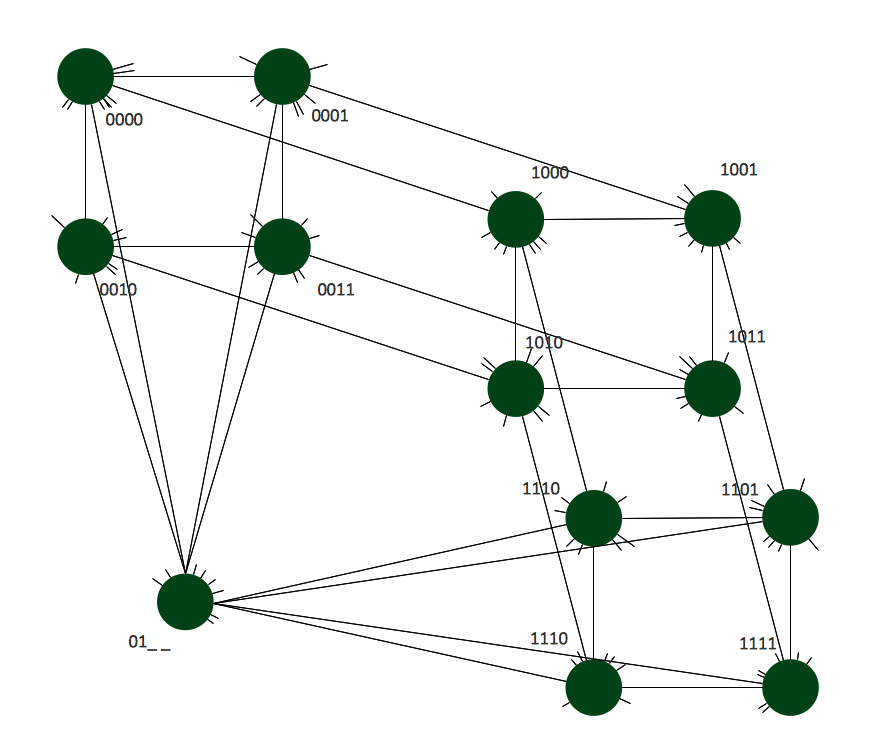
Hypercube Network Topology
- Mesh Network Topology Diagram | Vehicular ad - hoc network ...
- Vehicular ad - hoc network | Vehicular Networking | Design elements ...
- Diagrams Of Ad Hoc Network
- Vehicular ad - hoc network
- Visible light communication | Vehicular ad - hoc network | Global ...
- Vehicular ad - hoc network | Local vehicular networking - Vector ...
- Vehicular ad - hoc network | Road Transport - Design Elements ...
- Wireless Ad Hoc Network
- Vehicular Networking | How to Create a Vehicular Network Diagram ...
- Design elements - Local vehicular networking | Adhoc Wifi Diagram
- Automatic vehicle location | Vehicular ad - hoc network | Drawn Cell ...
- Vehicle Network
- Ad Hoc Wireless Network
- Vehicular Ad Hoc Networks
- Road Transport - Design Elements | 3D pictorial street map ...
- Vehicular Networking | UML Class Diagram Example
- Aerospace and Transport | Road Transport - Design Elements ...
- Ad Hoc Network Architecture Diagram
- Design elements - Local vehicular networking | Local area network ...
- Adhoc Networks Wlan