UML Class Diagram Notation

UML Flowchart Symbols

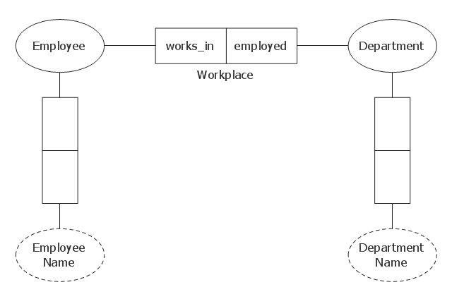
Entity Relationship Diagram Symbols

What Is a Circle Spoke Diagram

UML Class Diagram Constructor

UML Class Diagram. Design Elements

Entity Relationship Diagram - ERD - Software for Design Chen ER Diagrams
_Win_Mac.png "Entity Relationship Diagram - ERD - Software for Design <br>Chen ER Diagrams *")
Bank UML Diagram

Banking System

What is Entity-Relationship Diagram

UML Tool & UML Diagram Examples

This object-role modeling (ORM) diagram sample was designed on the base of the Wikimedia Commons file: Orm modell beispiel.gif. [commons.wikimedia.org/ wiki/ File:Orm_ modell_ beispiel.gif]
"Object-role Modeling (ORM) is a fact-oriented modeling approach for expressing, transforming and querying information at a conceptual level. Unlike Entity-Relationship modeling and Unified Modeling Language class diagramming, fact-oriented modeling is attribute-free, treating all elementary facts as relationships expressed in natural language sentences. For information modeling, ORM graphical notations are typically far more expressive than other notations, and ORM’s attribute-
free nature promotes semantic stability and facilitates natural verbalization." [www.orm.net/ pdf/ ORM2_ TechReport1.pdf]
The object-role model example "Object role modeling example" was designed using ConceptDraw PRO software extended with ORM Diagrams solution from Software Development area of ConceptDraw PRO Solution Park.
ORM diagram
Diagramming Software for Design UML Activity Diagrams


Electrical Diagram

Examples for OOSE Method

UML Diagram for System

UML Package Diagram. Design Elements

UML in 10 mins

Data Modeling with Entity Relationship Diagram

UML Sequence Diagram Example. SVG Vectored UML Diagrams Tools

- ERD Symbols and Meanings | Entity Relationship Diagram Symbols ...
- UML Class Diagram Notation | UML Tool & UML Diagram Examples ...
- UML Class Diagram Example for GoodsTransportation System ...
- Class Diagram For Hospital Management System Pdf
- UML Class Diagram Notation
- IDEF0 Flowchart Symbols | User Interface Design Examples | UML ...
- UML Use Case Diagram Example Registration System | UML Class ...
- Bank Sequence Diagram | UML Sequence Diagram | Bank System ...
- Class Diagram For Event Management System Pdf
- UML Class Diagram Notation | Example of DFD for Online Store ...
- Entity Relationship Diagram Symbols | UML Class Diagram Notation ...
- Components of ER Diagram | ERD Symbols and Meanings | UML ...
- Basic Flowchart Symbols and Meaning | Process Flowchart | UML ...
- UML Class Diagram Example - Medical Shop | UML Class Diagram ...
- Data Flow Diagram Symbols . DFD Library | Example of DFD for ...
- Bank Management System With Uml Ppt Pdf
- UML Collaboration Diagram (UML2.0) | UML Component Diagram ...
- UML Use Case Diagram Example . Registration System | UML ...
- Diagramming Software for Design UML Collaboration Diagrams ...
- Flowchart Software | UML Tool & UML Diagram Examples | UML ...