Cisco People. Cisco icons, shapes, stencils and symbols

Cisco WAN. Cisco icons, shapes, stencils and symbols

Cisco Network Diagram Software

Network Icon

Network Diagramming Software for Design. Cisco Network Diagrams


Wireless Network Drawing

Metropolitan area networks (MAN). Computer and Network Examples
. Computer and Network Examples")
Mechanical Design Software

Toroidal Network Topology

ERD Symbols and Meanings


Is ConceptDraw DIAGRAM an Alternative to Microsoft Visio?

VoIP

Hybrid Network Topology

The vector stencils library "Computers and network isometric" contains 56 3D icon symbols of computer and network devices.
Use these equipment shapes for drawing diagrams of computer and telecommunication networks, LAN, MAN and WAN architecture, physical and logical topology, wiring schematic and cabling layout plans.
This clipart library for the ConceptDraw PRO diagramming and vector drawing software is included in the Computer and Networks solution from the Computer and Networks area of ConceptDraw Solution Park.
3D Computers and network icons
How to Draw a Computer Network Diagrams

Entity Relationship Software

 AWS Architecture Diagrams
AWS Architecture Diagrams with powerful drawing tools and numerous predesigned Amazon icons and AWS simple icons is the best for creation the AWS Architecture Diagrams, describing the use of Amazon Web Services or Amazon Cloud Services, their application for development and implementation the systems running on the AWS infrastructure. The multifarious samples give you the good understanding of AWS platform, its structure, services, resources and features, wide opportunities, advantages and benefits from their use; solution’s templates are essential and helpful when designing, description and implementing the AWS infrastructure-based systems. Use them in technical documentation, advertising and marketing materials, in specifications, presentation slides, whitepapers, datasheets, posters, etc.
The vector stencils library "Telecom equipment" contains 11 hardware clipart icons of telecommunication devices for drawing computer network diagrams and equipment layouts.
"In telecommunication, a communications system is a collection of individual communications networks, transmission systems, relay stations, tributary stations, and data terminal equipment (DTE) usually capable of interconnection and interoperation to form an integrated whole. The components of a communications system serve a common purpose, are technically compatible, use common procedures, respond to controls, and operate in union. Telecommunications is a method of communication." [Communications system. Wikipedia]
"A basic telecommunication system consists of three primary units that are always present in some form: (1) A transmitter that takes information and converts it to a signal. (2) A transmission medium, also called the "physical channel" that carries the signal. ... (3) A receiver that takes the signal from the channel and converts it back into usable information." [Telecommunication. Wikipedia]
The clip art example "Telecom equipment - Vector stencils library" was created using the ConceptDraw PRO diagramming and vector drawing software extended with the Telecommunication Network Diagrams solution from the Computer and Networks area of ConceptDraw Solution Park.
Andrew multiband high / low power splitter

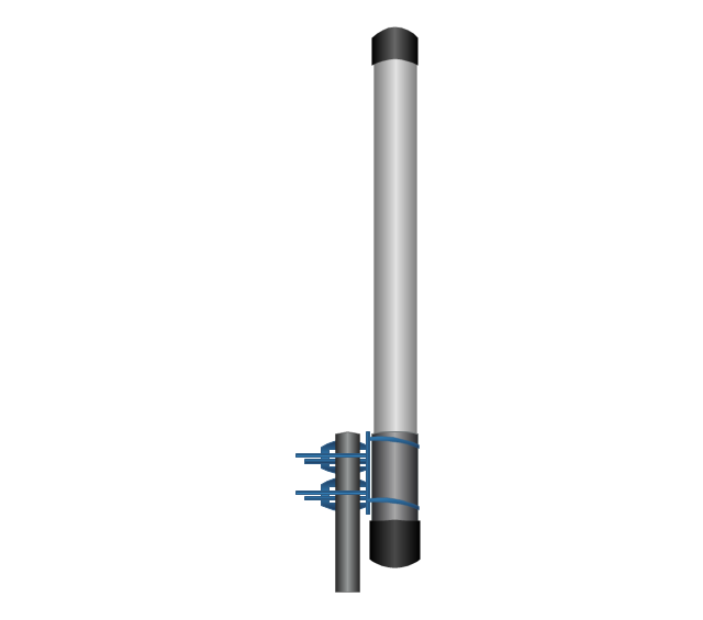
Andrew multi-band indoor omnidirectional antenna

Panel sector directional antenna

Omni directional antenna
Yagi directional antenna
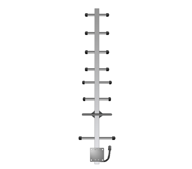
Yagi integrated downconverter

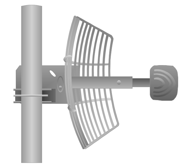
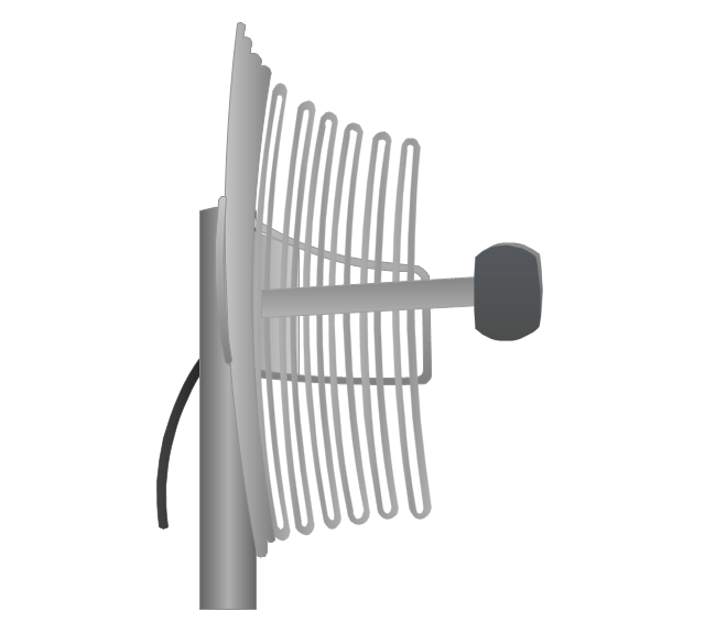
Grid antenna
Loop antenna
FireTide HotPort® 6000 wireless mesh nodes
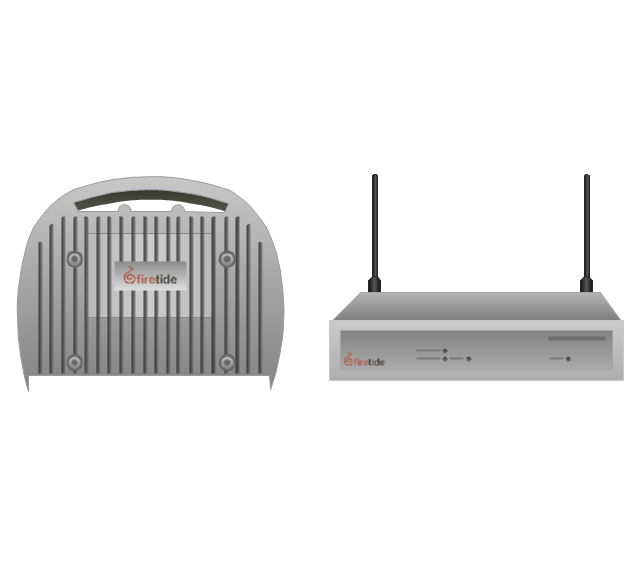
FireTide HotPoint® wireless access point
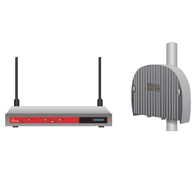
FireTide HotClient Customer Premises Equipment (CPE)
-telecom-equipment---vector-stencils-library.png--diagram-flowchart-example.png)
Network Diagram Software Enterprise Private Network

Network Topologies


- Cisco Routers . Cisco icons , shapes, stencils and symbols | Network ...
- Wireless Router
- Cisco Network Topology. Cisco icons , shapes, stencils and symbols ...
- 3d Network Icons
- Cisco Security. Cisco icons , shapes, stencils and symbols | Wireless ...
- How To use Switches in Network Diagram | Cisco Switches and ...
- Cisco IBM. Cisco icons , shapes, stencils and symbols | Design ...
- Cisco Security. Cisco icons , shapes, stencils and symbols | Cisco ...
- AWS Analytics - Vector stencils library | Design elements - AWS ...
- Cisco Network Diagrams | Cisco Network Templates | How to Create ...
- Design elements - IVR people | Cisco Network Design. Cisco icons ...
- Cisco Switches and Hubs. Cisco icons , shapes, stencils and ...
- Create Block Diagram | Computer Network Diagrams | Cisco ...
- Cisco Multimedia, Voice, Phone. Cisco icons , shapes, stencils and ...
- Cisco Network Topology. Cisco icons , shapes, stencils and symbols ...
- Visio Stencils Radio
- Cisco IBM. Cisco icons , shapes, stencils and symbols | Basic ...
- Cloud Computing Architecture Diagrams | Cisco WAN. Cisco icons ...
- OSPF Network. Computer and Network Examples | Cisco WAN ...
- Cisco IBM. Cisco icons , shapes, stencils and symbols | UML ...