Booch OOD Diagram

UML for Software Engineers
About UML

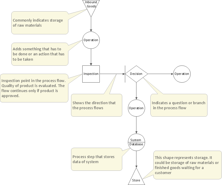
UML Flowchart Symbols

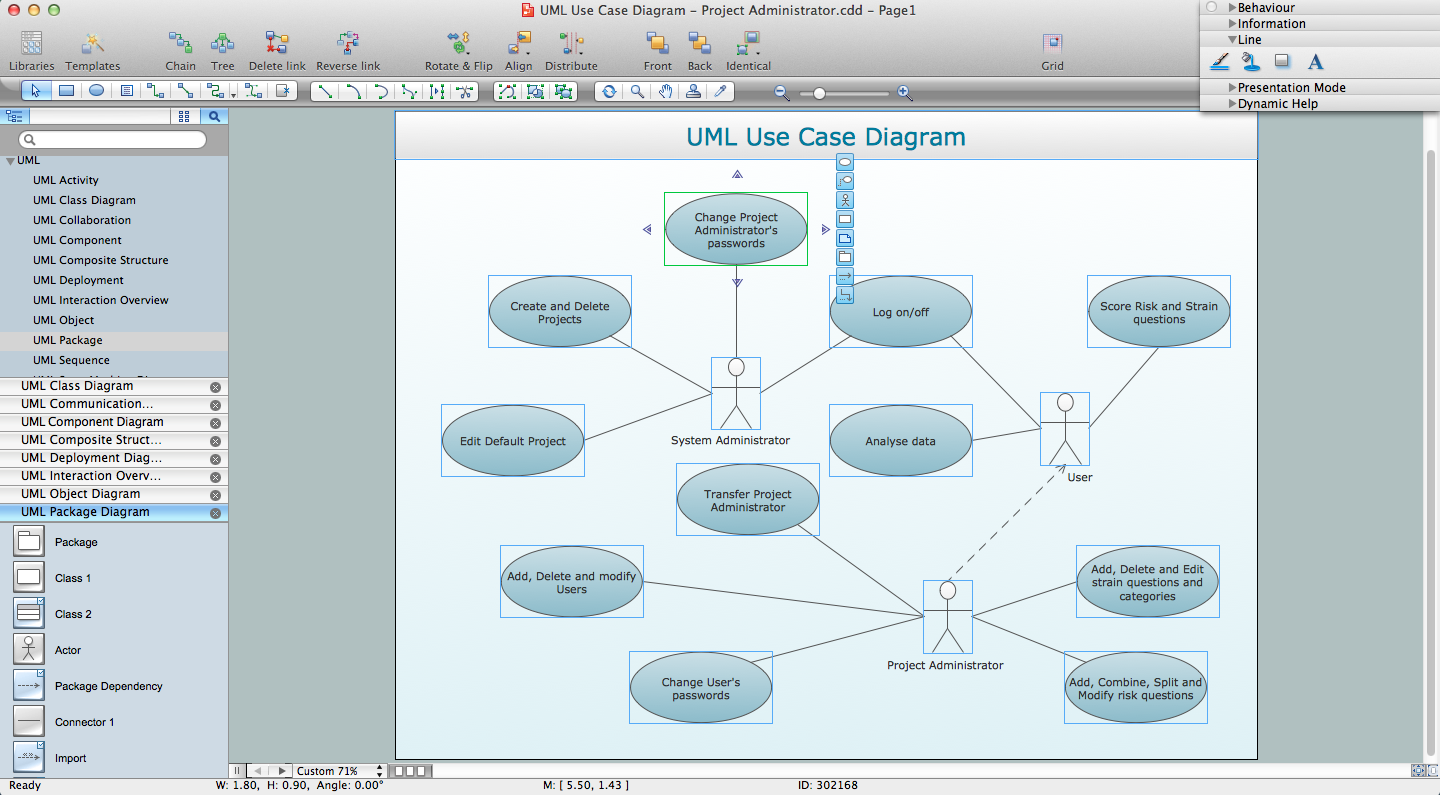
Jacobson Use Cases Diagram

DFD Flowchart Symbols

Structured Systems Analysis and Design Method (SSADM) with ConceptDraw DIAGRAM

SSADM Diagram

Gane Sarson Diagram

IDEF0 Diagram

IDEF0 Flowchart Symbols

Software Diagrams

Management Tools — Total Quality Management
Software and Database Design with ConceptDraw DIAGRAM

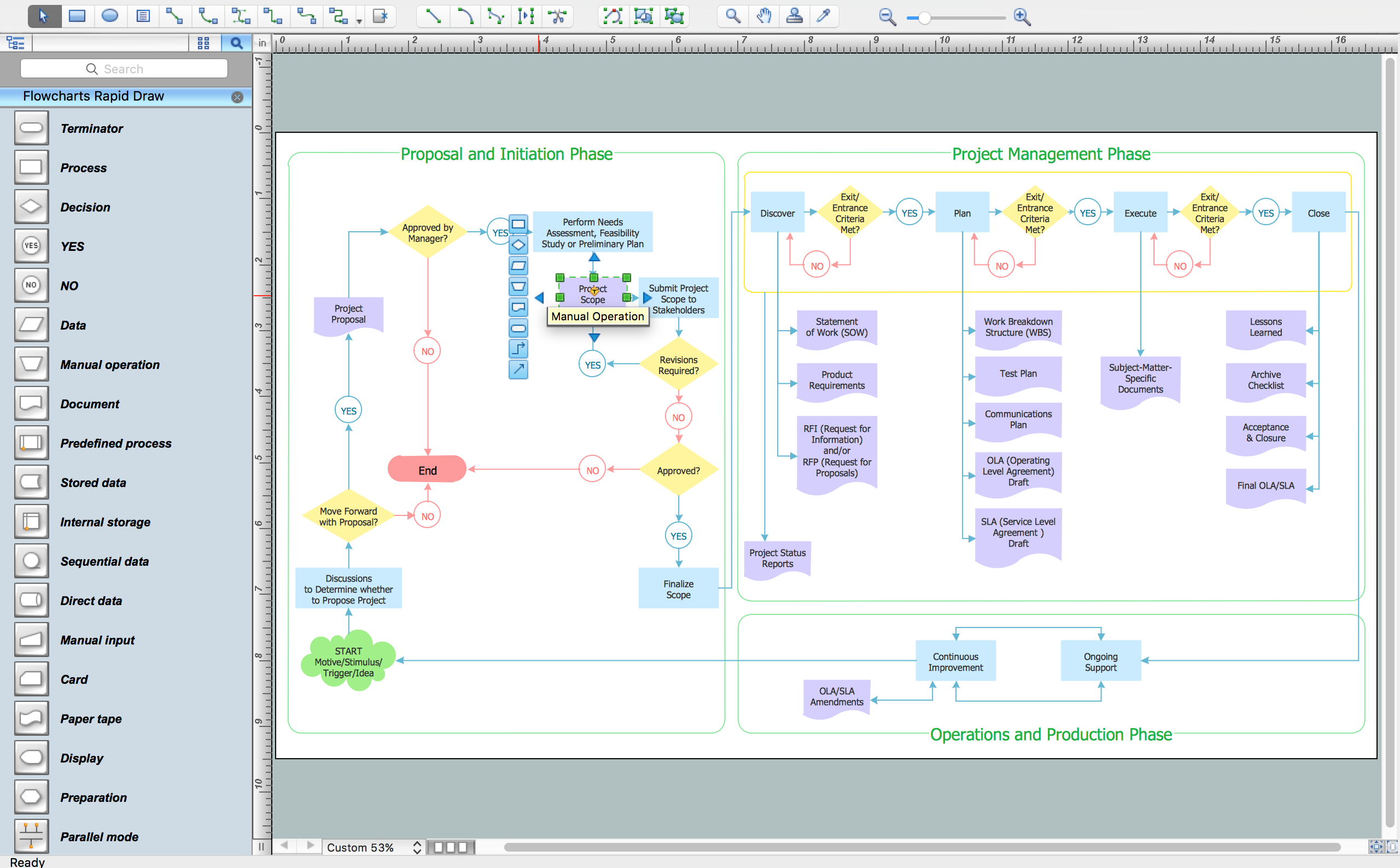
How To Create a FlowChart using ConceptDraw
- Explain Booch Modeling Technique In Detail
- Object-Oriented Development (OOD) Method | Booch OOD Diagram ...
- Booch OOD Diagram | Object-Oriented Development (OOD) Method ...
- Booch OOD Diagram | UML for Software Engineers | OOSE Method ...
- Booch Oo Design Model
- Booch OOD Diagram | OOSE Method | UML for Software Engineers ...
- Booch OOD Diagram | OOSE Method | UML for Software Engineers ...
- Booch OOD Diagram | OOSE Method | Examples for OOSE Method ...
- OOSE Method | Examples for OOSE Method | Booch OOD Diagram ...
- Booch OOD Diagram | Software Diagrams | Yourdon and Coad ...
- Software Modeling Language
- Yourdon and Coad Diagram | Booch OOD Diagram | Design Data ...
- Timing diagram | Diagramming Software for Design UML Timing ...
- Booch OOD Diagram | Coad/Yourdon's Object-Oriented Analysis ...
- DFD Flowchart Symbols | Jacobson Use Cases Diagram | Booch ...
- Unified Modeling Language Diagram
- Database Design | Booch OOD Diagram | UML Flowchart Symbols ...
- Object-Oriented Design | IDEF | OOSE Method | Object Oriented ...
- Sequence Diagram In Software Engineering
- Software and Database Design with ConceptDraw PRO | Booch ...