Booch OOD Diagram

Object-Oriented Development (OOD) Method

Examples for OOSE Method

UML for Software Engineers
Object-Oriented Design
About UML

Software Diagrams

Yourdon and Coad Diagram

Management Tools — Total Quality Management
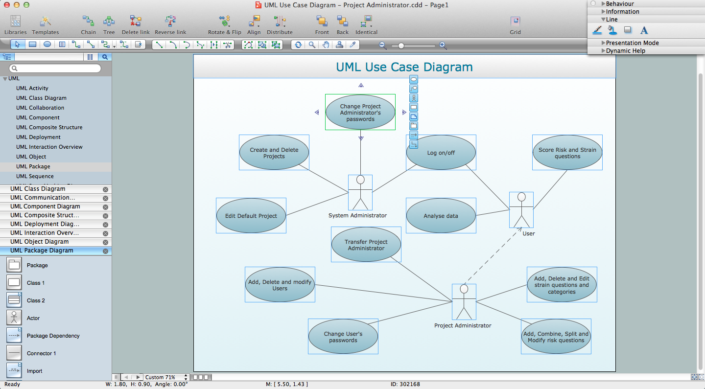
UML Diagramming Software

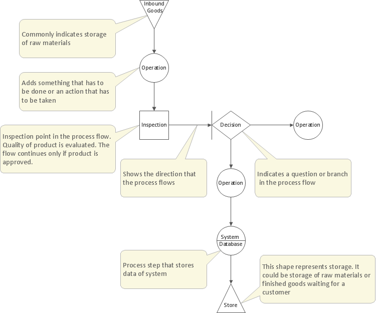
UML Flowchart Symbols

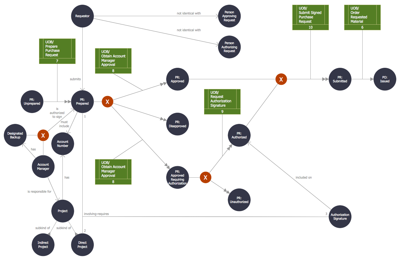
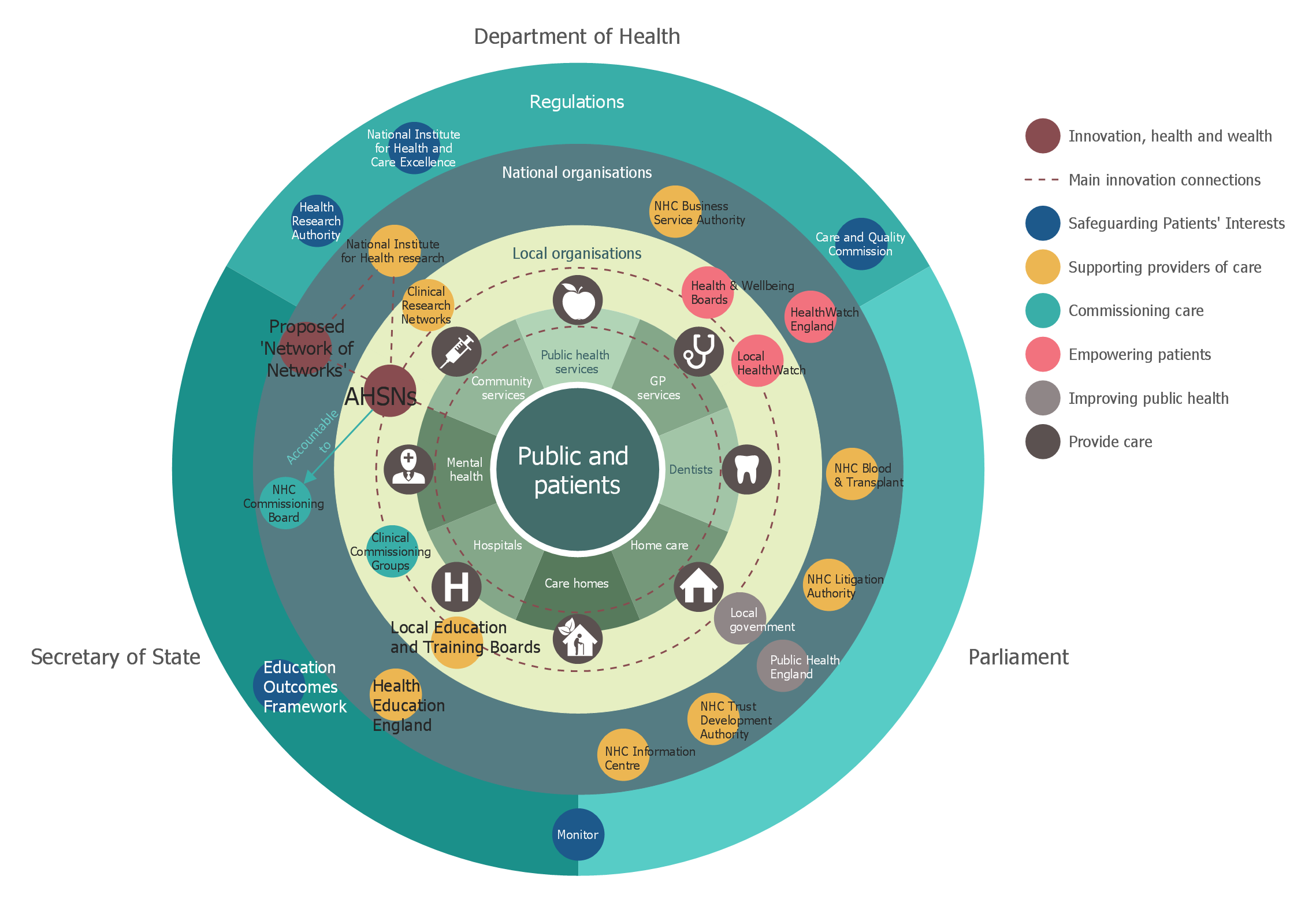
Stakeholder Onion Diagrams
DFD Flowchart Symbols

Diagramming Software for Design UML State Machine Diagrams


Structured Systems Analysis and Design Method (SSADM) with ConceptDraw DIAGRAM

- Booch OOD Diagram | Object-Oriented Development (OOD) Method ...
- Booch Methodology In Ooad
- Steps To Draw Sequence Dia Using Grady Booch Methodology
- Booch OOD Diagram | UML for Software Engineers | OOSE Method ...
- Example For Booch Methodology Using Dfd
- Booch OOD Diagram | OOSE Method | UML for Software Engineers ...
- Booch Methodology In Ooad Ppt
- Object-Oriented Development (OOD) Method | Booch OOD Diagram ...
- Booch OOD Diagram | OOSE Method | Examples for OOSE Method ...
- Explain Booch Method Includes Six Types Of Diagrams
- Methodology For Object Oriented Design Booch And Chen And Chen
- Booch OOD Diagram | Software Diagrams | ER Diagram Tool ...
- Gane Sarson Diagram | Booch OOD Diagram | Basic Flowchart ...
- Booch OOD Diagram | Examples Of Omt Methodology
- Object-Oriented Design | Booch OOD Diagram | Coad/Yourdon's ...
- Software Diagrams | UML Business Process | Software development ...
- UML sequence diagram - GET request | Booch OOD Diagram | UML ...
- Booch OOD Diagram | Coad/Yourdon's Object-Oriented Analysis ...
- The Booch Methodology In Oom
- Memory Object Diagram | Program Structure Diagram | Booch OOD ...