Venn Diagram Examples for Problem Solving
Sometimes the problems cannot be solved as easily as we want them to be, so for making it easier to understand them in order to simplify the tasks, it is better to create a diagram. In this way, with the help of a drawing, it can become clear what to focus on as well as what aspects to pay more attention to.
Having the examples of the problem-solving process in a way of a Venn diagram may lead to making it possible to create the needed scheme of what should be done as well as what work should be finished first within some project or an organization as a whole.
Any Venn diagram can also be called as a primary one. The other names for it are logic diagram, set diagram, etc. It is simply one of the so many types of the diagrams that are used for showing all the possible logical relations between some finite collection of a few or a lot of the different sets.
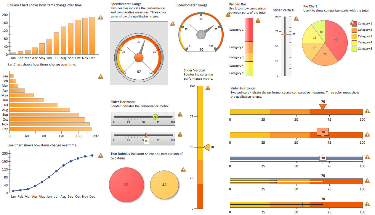
Example 1. Venn Diagram Problem Solving
The mentioned type of diagrams can be also used for depicting different elements in a way of the points in the plane as well as the sets in a way of the regions that can be found inside some closed curves. Any Venn diagram created with the help of the ConceptDraw DIAGRAM software may consist a lot of the overlapping closed curves such as circles, each of which is known for representing some set.
The mentioned points inside each of the curves are labelled with a letter “S” representing the elements of the set S in this way. At the same time, the points that can be found outside the boundary, are those which represent the elements which cannot be found in the “S” set.
In this way, the set of all the existing elements (which are known to be members of both sets S and T) can be represented in a visual way by the area of the overlap of the “T” and “S” regions.
In Venn diagrams the curves are usually overlapped in the way its creator wants them to be, showing all the possible relations in between the previously described sets. The mentioned “Venn diagrams” were conceived by John Venn in about 1880.
Since then, they are used for teaching the so-called “elementary set theory”. Besides, they can be also used for illustrating some simple set relationships in either logic, statistics, probability, linguistics or computer science, or both.
Any Venn diagram in which the area of each of its shapes seems to be proportional to the number of all the elements that it contains, is known to be called as a “scaled” or an “area-proportional” Venn diagram that is being constructed with the simple closed curves drawn in a plane.
The principle of all the Venn diagrams is that the sets (also known as “classes”) can be represented by regions in a special relation to one another. Due to such relation, all the possible logical relations of the mentioned classes can be indicated in the very same diagram showing the connections to each other.
In this way, the diagram leaves enough room for any possible relation of the classes to illustrate, and the given (or “actual”) relation can be after specified by indicating that some region is either not-null or null.
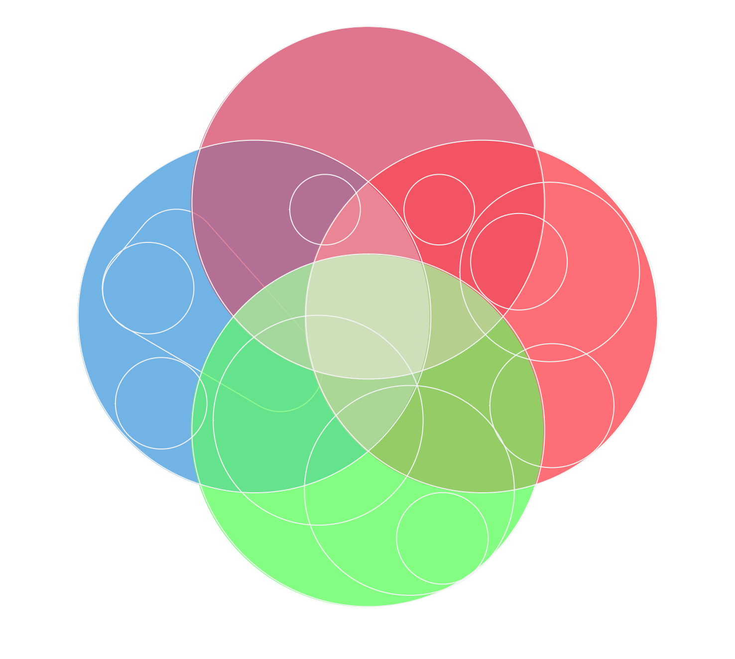
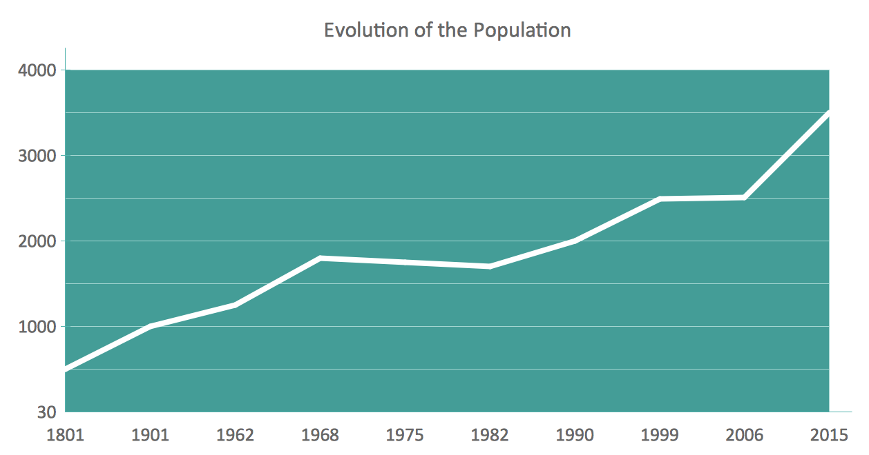
Example 2. Venn Diagram Problem Solving
Venn diagrams usually are those that comprise the overlapping circles and the interior of such circles can symbolically represent all the elements that the set includes. At the same time, the exterior is known to be representing those elements that are not members of the set and so they are not connected with it at all.
After being introduced by John Venn in 1880, the Venn diagrams were further developed in the 20th century. Thus, in 1963 D. W. Henderson showed that the existence of an n-Venn diagram that has n-fold rotational symmetry implied that n was a key number, called as “prime”. It was also showed that all symmetric Venn diagrams exist when n is either 7 or 5.
Venn diagrams are known to be similar to Euler diagrams, but still the first ones are more commonly used and many of those who made them know, that each of such diagrams for n component sets has to contain all 2n possible zones that are known to be corresponding to some combination of either exclusion or inclusion in each of the existing component sets.
It is also widely known that, to compare to the Venn diagrams, the Euler ones contain only the actually possible zones in some given context, but both Euler diagrams as well as Venn diagrams were incorporated as part of instruction in a so-called “set theory” in the 1960s as part of the new math movement. Since then, they have also been adopted in the curriculum of many other fields and nowadays they can be used for most of the needed problem-solving processes as long as there is enough information to add to them.
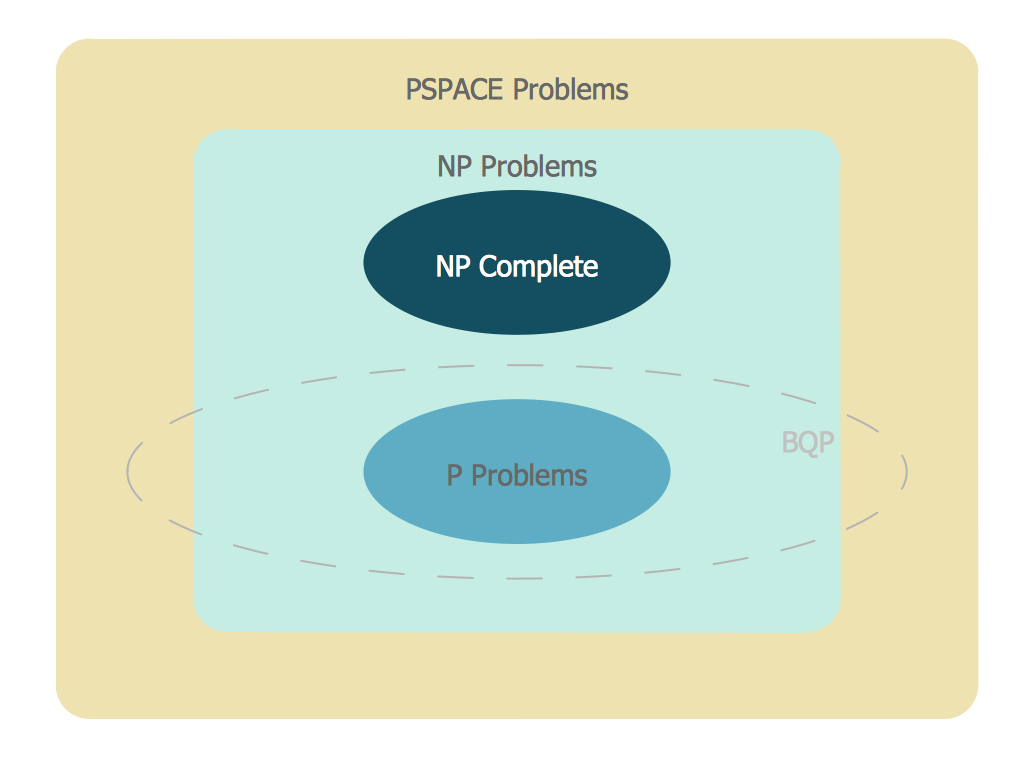
Example 3. Venn Diagram Problem Solving — BQP Complexity. The suspected relationship of BQP to other problem spaces.
In the Business Diagrams solution, there are the pre-made examples that can be always used for making the unique, great looking diagrams, such as the 2-set Venn ones of any needed colour, the 3-set one, the 4-set ones and the 5-set ones. Having the already previously created samples of the Venn diagrams can help any ConceptDraw DIAGRAM user make it possible to make the needed drawing within only a few minutes by editing the existing ones.
Taking this opportunity of using the already previously design diagrams, such as the Venn ones from the Business Diagrams solution, can simplify your work of the drawings and save your time. One of the examples, that is available for all the ConceptDraw DIAGRAM users is the “Venn Diagram — Internet Marketing Professions”. Next, the “Venn Diagram — Path to Sustainable Development” is another template of the Venn diagram created by using three circles where such notes as “Environmental”, “Social” and “Economic” are used.
TEN RELATED HOW TO's:
Use of various charts, diagrams and infographics is the most effective way of visual presenting information about healthy foods, healthy eating and healthy diet. ConceptDraw DIAGRAM diagramming and vector drawing software offers the Health Food solution from the Food and Beverage area of ConceptDraw Solution Park which is overfull of powerful drawing tools, libraries with ready-to-use vector objects and clipart, predesigned samples and examples which will help you easy design healthy foods illustrations.
Picture: Healthy Foods
Related Solution:
Working with information can be quite tedious, furthermore, some data can be quite difficult to perceive without any graphic representation. So, to facilitate your work, you can use business diagrams, such as simple flowcharts or Gantt charts for project management and orgcharts for clarifying your company structure. You can use a proper software, like ConceptDraw Pro, draw them on paper, or use whiteboards, but it is more convenient to use a digital tool.
This diagram shows a cross-functional flowchart that was made fore telecom service provider. A workflow of a common telecommunication service provider has a rather branched structure. Thus, it is useful to have a flow chart to visualize the sequences and interrelations of the work flow steps. Business process flowchart contains 17 processes and 4 decision points,that are distributed through 2 lines depicting the participants involved. Also there are connectors that show the data flow within processes. This flowchart displays a detailed model of the telecom service trading process, as well as all participants in the process and how they interact with each other.
Picture: Business diagrams & Org Charts with ConceptDraw DIAGRAM
A requisition form is one of the documents used for accounting in different manufacturing processes. There are two main types of requisition: a purchasing requisition and material requisition and difference between them is significant. Creating a flowchart might help you in understanding all the details of accounting process.
Flowcharts are a best visual method for dividing a large and complicated procedure into a several little clear pieces. The main value-ability of an effective flowchart is its simpleness. Material requisition flowcharts are used to document the process of relationships between the different departments and the purchasing department within an organization. The flow chart gives the step-by-step guide on how is carried out the procurement process of the materials necessary for the functioning of the organization. This type of flowchart along with many other business flowcharts, one can easy create using ConceptDraw Flowcharts solution.
Picture: Material Requisition Flowchart. Flowchart Examples
Related Solution:
E-Learning in Schools: Online Language Teaching tools. E-Learning software for remote presentations with Skype. Best practices for eLearning.
Picture: Language School E-Learning
Related Solution:
The knowledge and ability to apply various strategies for dealing with problems and difficult situations is very useful in many areas. The Fishbone strategy is one of the most progressive. This graphical technique helps to identify possible causes of problems, to set the goals, and also show internal connections between the different parts of problem. After reviewing all causes and facts, you can easily find right solution.
ConceptDraw DIAGRAM diagramming and vector drawing software extended with Fishbone Diagrams Solution from the Management Area of ConceptDraw Solution Park is a powerful Fishbone Problem Solving tool.
Picture: Fishbone Problem Solving
Related Solution:
Database structures are usually described by ER-diagrams which represents entities as boxes with lines-connections between them. You can create any entity-relationship diagram (ERD) by means of ConceptDraw DIAGRAM using ready-to-use templates and special libraries containing all the needed symbols and shapes. Creating a model for your database from now on can take just a few minutes.
ERD (entity relationship diagram) designed to show the logical structure of databases. It intended to depict the relationships between data components (entities). ERDs are a popular tool for software engineers and architects. Using ERD they can manage the every aspect of database design. Also ERD can be used as guidelines for testing and communications before software release. This diagram represents the file reference system of the WordPress web platform. Because entity relationship diagrams have such a broad application area through the prevalence of database technology, it can be applied for a wide range of users.
Picture: Entity-Relationship Diagram (ERD) with ConceptDraw DIAGRAM
Related Solution:
This sample shows the Flowchart of the ACC general account creation. This Flowchart describes the Start point, the process of the handling the user requests and the End point – creating of the account. The shapes represent the subprocesses and the arrows between the shapes shows the sequence of the actions.
This sample was created in ConceptDraw DIAGRAM diagramming and vector drawing software using the Flowcharts solution from the Diagrams area of ConceptDraw Solution Park.
Picture: Examples of Flowchart
Related Solution:
ConceptDraw DIAGRAM is a powerful software that helps you create professional looking cross-functional flowcharts with the well-designed objects. ConceptDraw DIAGRAM allows you to focus on work, not the drawing process. ConceptDraw Arrows10 Technology allows to draw connectors with smart behavior that gives flexibility to you during work process.
Picture: Horizontal Cross Functional Flowchart
Related Solution:
UML Timing Diagram as special form of a sequence diagram is used to explore the behaviours of objects throughout a given period of time.
Picture: Timing diagram
Related Solution:
Stakeholder management is a critical component to the successful delivery of any project, programme or activity.
ConceptDraw DIAGRAM is a powerful diagramming and vector drawing software. Now, thanks to the Stakeholder Onion Diagrams Solution included to the Management Area of ConceptDraw Solution Park, ConceptDraw DIAGRAM became also unique stakeholder management system design software.
Picture: Stakeholder Management System using Onion Diagram
Related Solution: