Made with
ConceptDraw
DIAGRAM 18

IDEF0 standard with ConceptDraw DIAGRAM

The activity of any organization is more or less branchy network of processes. The description of these processes is a hard technical task which requires definite methodology and standards.

For the first time this problem arose in the seventies of the past century during the development of complicated projects requested by the Air Forces of the USA. ICAM system (Integrated Computer-Aided Manufacturing) was developed and later on its basis there was developed the standard of structural description of IDEF0 processes. In 1993 the government of the USA accepted this standard as a federal standard.

In 2000 the new version of ISO 9000:2000 standards was accepted by International Organization of Standardization. The main idea of this standard is a representation of organization activity as a network of processes hence the management of organization is the management of this network of processes. It is for description of these networks the IDEF0 standard is used.

According to the IDEF0 standard any process can be described in the form of a block (Activity Box) which has inputs and outputs. The process consists in transformation of inputs into outputs under the influence of the management and in the presence of necessary resources. Outputs of the given process later on can be either inputs for the next process or resources, or management means.

IDEF0 diagram

Each side of the block has its meaning:

  • Top side - Control;
  • Left side - Input;
  • Right side – Output;
  • Bottom side – Mechanism.

Besides, each block on the diagram has its unique identification number. For instance, the optimization process of the initial code of the program product can be represented in the form of the following block in which already existing quick-and-dirty code is the input, technical task on modernization is the element of the process management, programmer and hardware are the modernization mechanism and at the output optimized code will result.

IDEF0 diagram

On the diagram an interaction between processes is presented by way of arrows, which connect outputs of one processes with inputs of others. Actually the diagram consists of only 2 elements: blocks-processes and arrows which connect them.

Depending on their position on the diagram arrows are classified into input and output arrows, arrows of mechanisms (resources) and management arrows. Besides, arrows can be distinguished by any other criteria. By prior agreement, for more pictorial presentation of consecution of processes, arrows can be marked out with color or with other line types (E.g. solid or dotted, thin or thick.) Various types of lines are used not only for obviousness like at presentations, for example. Also, using different arrow types it is possible to process the diagram of processes by means of computer programs and to get reports, which characterize the definite type of industrial process.

At composing the diagram of industrial processes the principal of decomposition is used, i.e. the complicated process is divided into small parts. The degree of the detailed elaboration is defined by the diagram developer. For instance, code optimizing process can be divided into constituents such as the optimization itself, results testing, bugs fixing, second testing and documenting of the new optimized code.

According to IDEF0 standard the process of diagram composing starts from presentation of the whole system as one block with a unique number A0. Besides the purpose of the diagram with the viewpoint in the form of the brief description are denoted. The definition of the diagram purpose allows choosing of processes which should be denoted and described on the given diagram, and the viewpoint defines the degree of the necessary detailed elaboration of these processes.

The diagram on which not detailed initial processes are represented is called a Parent diagram. The diagram of the detailed process from the Parent diagram is called a Child diagram. Correspondingly, the block which is worked out in detail in the Child diagram is the Parent Box, and all blocks which describe it in the Child diagram are Child Boxes.

Blocks numbers on the child diagrams begin with the number of the parent box. For example, if the parent box has number A15 then child boxes will have numbers A151, A152 and so on.

Accordingly to IDEF0 standard for description of notations and expressions used in the diagram, a glossary is used. For example, the notation of the computer Mac1 which is used as a mechanism may contain the description of computer parameters.

IDEF0 standard with ConceptDraw DIAGRAM *

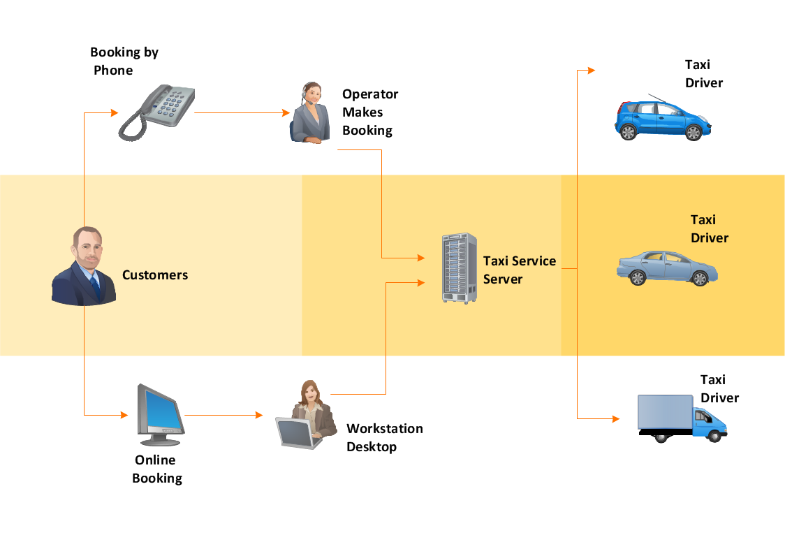
Example 1. IDEF0 standard diagram example (Mac OS X and Windows)

This IDEF0 diagram shows a detailed description of an application-development process. The steps of this process are represented by blocks which are visually arranged according to their logical levels.

All source documents are vector graphic documents. They are available for reviewing, modifying, or converting to a variety of formats (PDF file, MS PowerPoint, MS Visio, and many other graphic formats).


TEN RELATED HOW TO's:
Flowcharts can be used in designing and documenting both simple and complex processes or programs and, similar to the other types of diagrams, they can help visualize what happens and so help understand some definite process, and, as a result, find flaws, bottlenecks and other features within it.Flowchart Programming Project
Picture: Flowchart Programming Project. Flowchart Examples
Related Solution:
Database structures are usually described by ER-diagrams which represents entities as boxes with lines-connections between them. You can create any entity-relationship diagram (ERD) by means of ConceptDraw DIAGRAM using ready-to-use templates and special libraries containing all the needed symbols and shapes. Creating a model for your database from now on can take just a few minutes. ERD (entity relationship diagram) designed to show the logical structure of databases. It intended to depict the relationships between data components (entities). ERDs are a popular tool for software engineers and architects. Using ERD they can manage the every aspect of database design. Also ERD can be used as guidelines for testing and communications before software release. This diagram represents the file reference system of the WordPress web platform. Because entity relationship diagrams have such a broad application area through the prevalence of database technology, it can be applied for a wide range of users.Entity-Relationship Diagram (ERD) <br>with ConceptDraw DIAGRAM  *
Picture: Entity-Relationship Diagram (ERD) with ConceptDraw DIAGRAM
Related Solution:
There are numerous articles about the advantages of flowcharting, creating business graphics and developing different charts. Nevertheless, these articles are almost useless without the main component - the examples of flowcharts, org charts and without a fine example, it is difficult to get all the conveniences of creating diagrams. You can find tons of templates and vivid examples on Solution Park. This illustration shows a variety of business diagrams that can be created using ConceptDraw DIAGRAM. It comprises a different fields of business activities: management, marketing, networking, software and database development along with design of infographics and business illustrations. ConceptDraw DIAGRAM provides a huge set of sample drawings including business process modeling diagrams,, network diagrams, UML diagrams, orgcharts, DFD, flowcharts, ERD, geographical maps and more.Examples of Flowcharts, Org Charts and More
Picture: Examples of Flowcharts, Org Charts and More
Related Solution:
Create with our data flow diagram software perfect data flow diagrams. Download data flow diagram software for FREE. Use hundreds of data flow diagram examples.Collaboration in a Project Team *
Picture: Collaboration in a Project Team
When trying to figure out the nature of the problems occurring within a project, there are many ways to develop such understanding. One of the most common ways to document processes for further improvement is to draw a process flowchart, which depicts the activities of the process arranged in sequential order — this is business process management. ConceptDraw DIAGRAM is business process mapping software with impressive range of productivity features for business process management and classic project management. This business process management software is helpful for many purposes from different payment processes, or manufacturing processes to chemical processes. Business process mapping flowcharts helps clarify the actual workflow of different people engaged in the same process. This samples were made with ConceptDraw DIAGRAM — business process mapping software for flowcharting and used as classic visio alternative because its briefly named "visio for mac" and for windows, this sort of software named the business process management tools. This flowchart diagram shows a process flow of project management. The diagram that is presented here depicts the project life cycle that is basic for the most of project management methods. Breaking a project into phases allows to track it in the proper manner. Through separation on phases, the total workflow of a project is divided into some foreseeable components, thus making it easier to follow the project status. A project life cycle commonly includes: initiation, definition, design, development and implementation phases. Distinguished method to show parallel and interdependent processes, as well as project life cycle relationships. A flowchart diagram is often used as visual guide to project. For instance, it used by marketing project management software for visualizing stages of marketing activities or as project management workflow tools. Created with ConceptDraw DIAGRAM — business process mapping software which is flowcharting visio alternative or shortly its visio for mac, this sort of software platform often named the business process management tools.Process Flowchart
Picture: Process Flowchart: A Step-by-Step Comprehensive Guide
Related Solution:
The activity of any organization is more or less branchy network of processes. The description of these processes is a hard technical task which requires definite methodology and standards. According to the IDEF0 standard any process can be described in the form of a block (Activity Box) which has inputs and outputs. The process consists in transformation of inputs into outputs under the influence of the management and in the presence of necessary resources. Outputs of the given process later on can be either inputs for the next process or resources, or management means.IDEF0 standard with ConceptDraw DIAGRAM *
Picture: IDEF0 standard with ConceptDraw DIAGRAM
Related Solution:
Use tools of ConceptDraw DIAGRAM software to create the Organigram HR, show how the entire company, introduce the competency-based management, and analyze whether new staff positions are necessary to be created or there are some gaps to be filled.Organigram HR Design in ConceptDraw DIAGRAM
Picture: Organigram HR
Related Solution:
To your mind, deliberation about the profits of creating organizational charts takes more time than actually creating itself. If lack of software is the only thing that stops you, you should know that organizational charts with ConceptDraw DIAGRAM are created within a few minutes. Owing to the great number of ready-to-use templates, you’ll get your chart easily. Chart is a very handy format for visually depicting official relations of an organization. Usually, an Orgchart (organizational chart) consists from simple geometrical shapes, containing an information on a position, personal data, and the lines that means responsibilities and accountabilities associated with position. ConceptDraw solution designed for making organizational charts enables one to create various org charts effortlessly using special templates and vector libraries.Organizational Charts with ConceptDraw DIAGRAM  *
Picture: Organizational Charts with ConceptDraw DIAGRAM
Related Solution:
ConceptDraw DIAGRAM extended with IDEF0 Diagrams solution from the Software Development area of ConceptDraw Solution Park is a powerful diagramming and vector drawing IDEF0 software. All IDEF0 diagrams created in ConceptDraw DIAGRAM are vector graphic documents and can be reviewed, modified and converted to MS Visio XML format. To obtain the IDEF0 Visio documents from ConceptDraw DIAGRAM documents use the wide export possibilities of ConceptDraw DIAGRAM.IDEF0 Visio *
Picture: IDEF0 Visio
Related Solution:
ConceptDraw DIAGRAM diagramming and vector drawing software extended with Mac OS User Interface Solution from the Software Development area is a powerful Mac OS GUI SoftwareMac OS GUI Software *
Picture: Mac OS GUI Software
Related Solution:
ConceptDraw
DIAGRAM 18