Line Chart Examples
Line and scatter graphsOne of the most popular and very commonly used charts is a line one, sometimes also called as a “line graph”. This type of chart helps to illustrate data displaying the needed to be represented information in a way of a series of data points. Such data points are known to be called as “markers”. The markers are connected with help of the straight line segments on the chart making it looking the way it should be — as a line chart. The mentioned chart is simply a very basic type of existing charts. It is used in many fields of business activity, including operating one, investing, financing one, etc. Any line chart may look very similar to a scatter one, apart from the existing measurement points, which are being ordered (usually by the “x-axis” value) as well as joined with help of the straight line segments. A “line chart” can be used for visualizing a trend in data over some intervals of time, known to be called as the “time series”. The line within the line graph can be drawn chronologically, resulting in the changing the name of the “line chart” to the “run one”. The data collected from the experiments in the experimental sciences is often known to be represented in a way of a graph, which can be any type, depending on which one is more convenient for it. Thus, "visualization" graph can be a great way of displaying the exact values as the measurements can be made visually, leading to more conclusions from the data. The Line Graphs Solution from ConceptDraw STORE application can be very useful for those who intend to create their own great looking line graphs as well as line charts. It provides the libraries with already previously created line charts that can be used as the drafts for some unique drawings made by all the ConceptDraw DIAGRAM users.
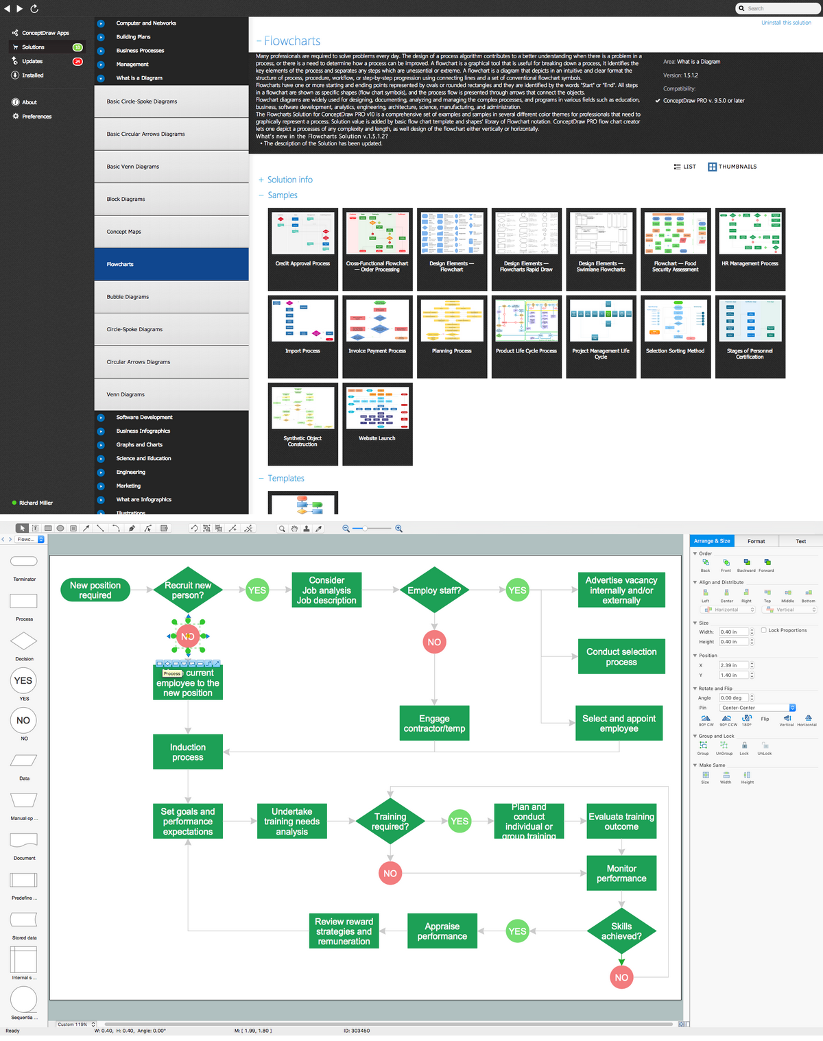
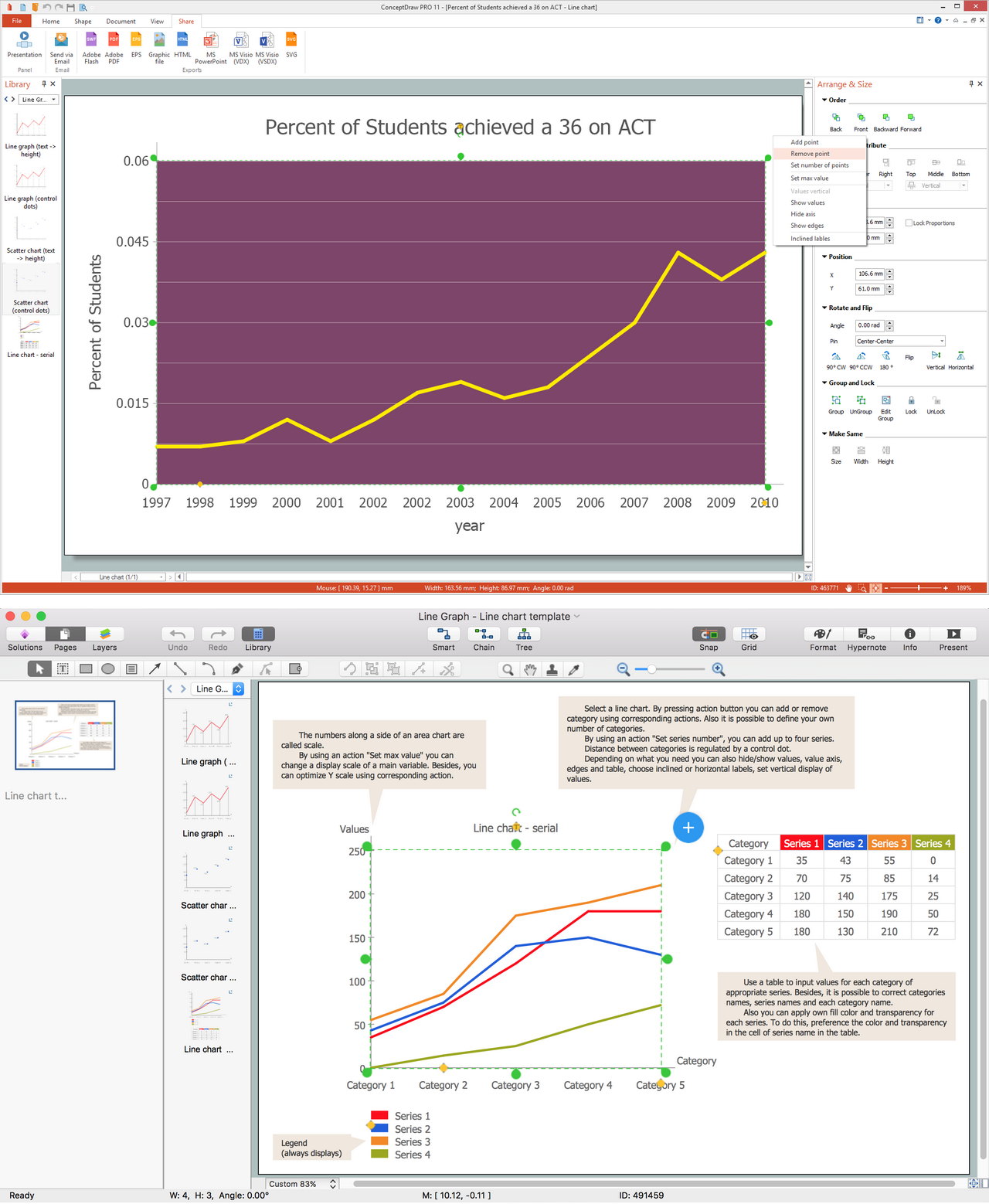
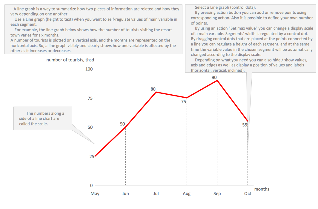
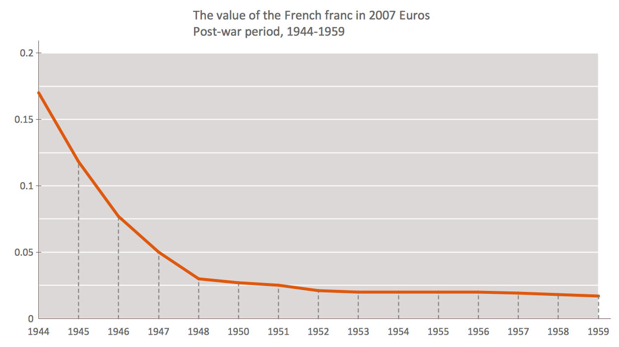
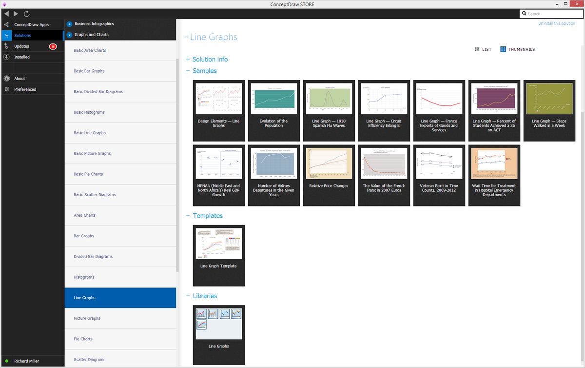
Example 1. Line Chart Solution in ConceptDraw STORE On this site, there’re a few examples of the line charts, such as the representation of the Annual Percentage Change where the percentages are shown on the Y axis and the years on the X axis. Thus, it is obvious to see all the changes in percentage during the period from 2010 up to 2014 year, for all four years in total which is convenient to learn from such graph as it is simpler to see the changes themselves. Another line graph on this site shows the circuit efficiency having the Link Efficiency represented on the Y axis and the Circuit on the X one. There are numbers from 0 up to 1,2 on the Link Efficiency axis and the positions on the “Circuit” one are the following: T1, E2, E3, T3, ATM1. Another example of the line graph from this site describes the value of the French franc in 2007 Euros Post-war period from 1944 up to 1959 year. There’s one mentioning the percentage of the students who achieved a 36 on ACT, where on the Y axis there are years mentioned: 1997, 1998, 1999, 2000, 2001, 2002, 2003, 2004, 2005, 2006, 2007, 2008, 2009, 2010 and 2011. The percentage starts with 0 going up to 0,06, but it is obvious that the highest percentage does not go upper the 0,045 point. There is also a line graph illustrating quantity of the departures of people using airplanes of the same company each year named Number of Airline Departures in the Given Years. The years on this line chart are mentioned starting from the 1996 one and all the way up to the last illustrated, 2002 year. The number of departures varies from 0 to 12, never exceeding 12. It becomes clear looking at such graph that the number of departures in 1996 was the lowest — about 7 a year, but this number was increased already by the next year which is more than 10 in 1997. The highest quantity of the departures was in 2000 when there were over 10, almost 12 ones. You can also find other examples of the line chart where the evolution of the population is mentioned, Thus, looking through the years, starting from 1801 going all the way up to 2015 we can see that it has been increasing reaching in the last year 3500. Apart from the mentioned examples on this page, there are also other samples which can be found in the ConceptDraw STORE application, in the “Line Graphs Solution”. One of them is called “Line chart - serial” where the values from 0 to 250 on the y axis are and where the different categories on the x axis are, named Category 1, Category 2, Category 3, Category 4 and Category 5. Thus, having different “Series” in different colours so it is obvious where each of them is on the line graph, we can see the representation of such data in a graphical way which is the most convenient for understanding, to compare the same data being read from the book. The mentioned line graph, as well as four more other line graphs, including the one named “Line Graph (text -> hight)” illustrating the “points” on its x axis from the 1st up to a 6th one, and the numbers from 0 up to 500 on the y axis, are there in the mentioned solution and all of them can be used as the drafts for your own drawings of the line graphs. The mentioned “Line Graph (text -> hight)” one shows the numbers on the line going from the Point 1 and 0 to 450 and on each of the mentioned tops there are the numbers with the values, such as 300, 200, 350, 250 and 450, being similar to another line chart from this solution — the “Line graph (control dots) one”. Having the pre-made templates is always very convenient as it means there’s no need to make some graph from a scratch, but to use the already existing layout. The professionally created templates of the line charts were all created by those who known to be the specialists in making such drawings and so having them as the examples for your own charts means ending up having your own professionally looking chart. 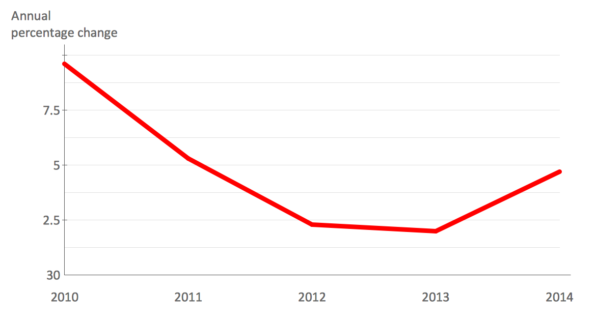 Line Graph - Anual Percentage Change Line Graph - Anual Percentage Change
 Line Graph - Line Graph - Values by Categories 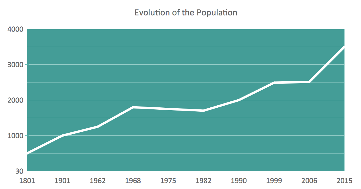 Line Graph - Line Graph - Time Series 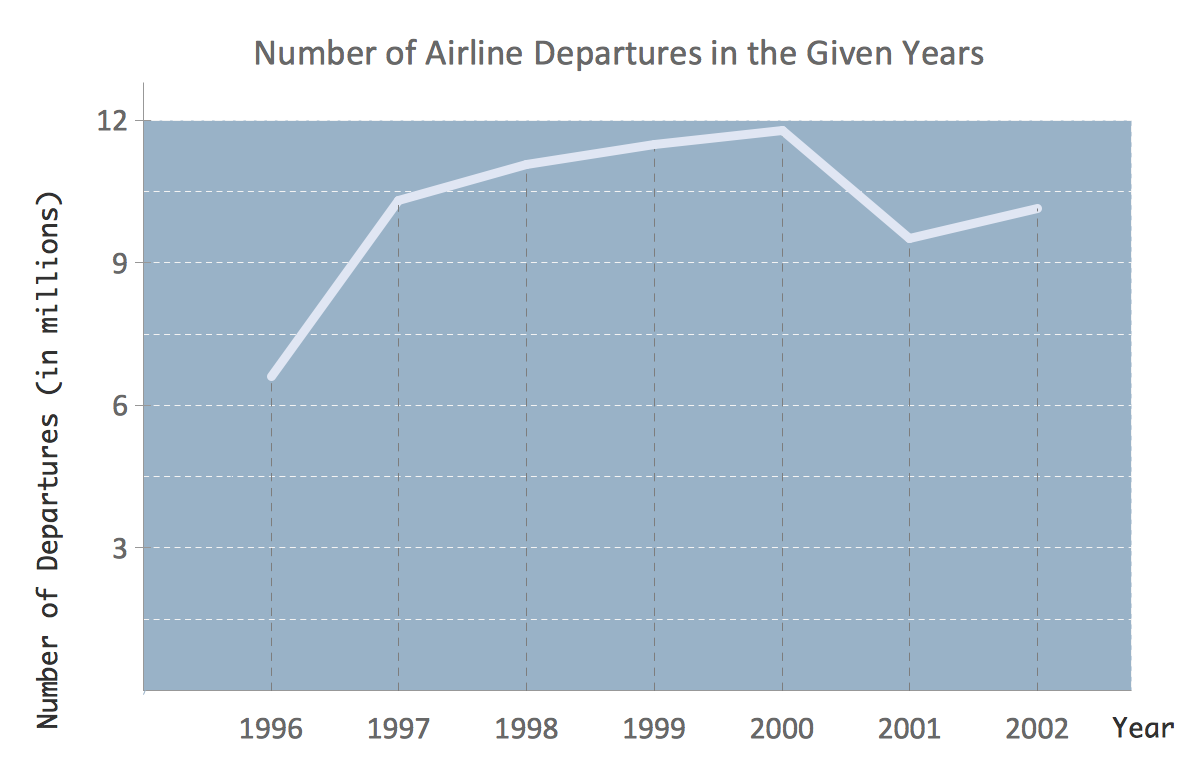 Line Graph - Line Graph - Time Series 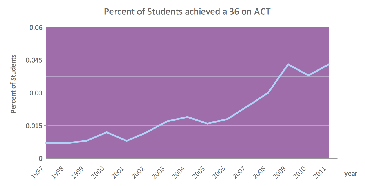 Line Graph - Anual Percentage Change Line Graph - Anual Percentage Change
 Line Graph - Line Graph - Time Series |
Example 2. Line chart example — Evolution of the Population.
Thinking about making a line chart (or line graph), you can be sure that the final result will always look simply smart as well as professional in case you use ConceptDraw DIAGRAM diagramming and drawing software as well as the solution from ConceptDraw STORE application — the “Line Graphs” one. Use it for making your own great looking Line Graphs and line charts for developing the business you are working in.