Use Case Diagrams technology with ConceptDraw DIAGRAM

Example of Flowchart Diagram

Basic Flowchart Symbols and Meaning


Jacobson Use Cases Diagram

IDEF0 Visio

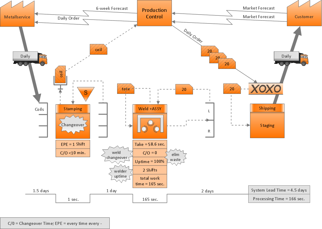
 Data Flow Diagrams (DFD)
Data Flow Diagrams solution extends ConceptDraw DIAGRAM software with templates, samples and libraries of vector stencils for drawing the data flow diagrams (DFD).
Software Diagram Examples and Templates

Software Development area of ConceptDraw Solution Park provides 5 solutions:
Data Flow Diagrams, Entity-Relationship Diagram (ERD), Graphic User Interface, IDEFO Diagrams, Rapid UML.
Model Based Systems Engineering

ConceptDraw Arrows10 Technology
- points;
- Connecting groups of objects;
- Auto-routing;
- Connectors text;
- Snap to Guides ;
- Quick.
Systems Engineering

ConceptDraw DIAGRAM supplied with SysML Solution from the Software Development Area of ConceptDraw Solution Park is a powerful and effective systems engineering software.
- Dfd Diagram For Restaurant Management System In Software
- Data Flow Diagram For Restaurant Management System
- Data Flow Diagrams (DFD) | Cafe and Restaurant Floor Plans ...
- Use case restaurant model | Use Case Diagrams technology with ...
- Restaurant Software Usecase Diagram
- IDEF0 Diagrams | Data Flow Diagrams (DFD) | IDEF Business ...
- Process Flowchart | | Flowchart Programming Project . Flowchart ...
- Draw An Er Diagram For Restaurant Management System
- Object-Oriented Design | Booch OOD Diagram | Coad/Yourdon's ...
- IDEF0 Flowchart Symbols | User Interface Design Examples | UML ...
- ERD | Entity Relationship Diagrams, ERD Software for Mac and Win
- Flowchart | Basic Flowchart Symbols and Meaning
- Flowchart | Flowchart Design - Symbols, Shapes, Stencils and Icons
- Flowchart | Flow Chart Symbols
- Electrical | Electrical Drawing - Wiring and Circuits Schematics
- Flowchart | Common Flowchart Symbols
- Flowchart | Common Flowchart Symbols