 Entity-Relationship Diagram (ERD)
An Entity-Relationship Diagram (ERD) is a visual presentation of entities and relationships. That type of diagrams is often used in the semi-structured or unstructured data in databases and information systems. At first glance ERD is similar to a flowch
 Fault Tree Analysis Diagrams
This solution extends ConceptDraw DIAGRAM.5 or later with templates, fault tree analysis example, samples and a library of vector design elements for drawing FTA diagrams (or negative analytical trees), cause and effect diagrams and fault tree diagrams.
 Interactive Voice Response Diagrams
Interactive Voice Response Diagrams solution extends ConceptDraw DIAGRAM software with samples, templates and libraries of ready-to-use vector stencils that help create Interactive Voice Response (IVR) diagrams illustrating in details a work of interactive voice response system, the IVR system’s logical and physical structure, Voice-over-Internet Protocol (VoIP) diagrams, and Action VoIP diagrams with representing voice actions on them, to visualize how the computers interact with callers through voice recognition and dual-tone multi-frequency signaling (DTMF) keypad inputs.
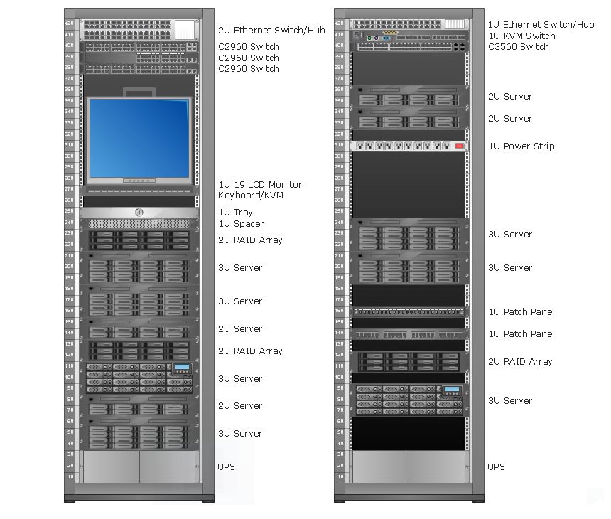
Rack Diagrams

Software development with ConceptDraw DIAGRAM

HelpDesk
How to Create an Entity-Relationship Diagram

- Er Diagram For Restaurant Management System Pdf
- Dfd Restaurant Management System
- Entity Relationship Diagram For Restaurant Management System
- Er Diagram For Restaurant Management System
- Er Diagram For Restaurant Management System Ppt
- Er Diagram Of Restaurant Management System
- Erd Diagram For Restaurant Management System
- Erd And Dfd Of Resturant Management System
- ER Diagram Restaurant Management System
- Data Flow Diagrams (DFD) | Accounting Information Systems ...
- Er Diagram For Restaurant Management Uml
- Management Information System Restaurant Diagrams
- Example Erd Of Restaurant System
- Er Representation Of Restaurant Management System
- Data Flow Diagram For Online Restaurant Management System
- Uml Diagrams Of Restaurant Management System
- Dfd For Restaurant Management System
- Entity-Relationship Diagram ( ERD ) | Technical Drawing Software ...
- Uml Diagrams For Restaurant Management System
- Dfd Diagram For Restaurant Management System