 Network Layout Floor Plans
Network Layout Floor Plans solution extends ConceptDraw DIAGRAM software functionality with powerful tools for quick and efficient documentation the network equipment and displaying its location on the professionally designed Network Layout Floor Plans. Never before creation of Network Layout Floor Plans, Network Communication Plans, Network Topologies Plans and Network Topology Maps was not so easy, convenient and fast as with predesigned templates, samples, examples and comprehensive set of vector design elements included to the Network Layout Floor Plans solution. All listed types of plans will be a good support for the future correct cabling and installation of network equipment.
Local area network (LAN). Computer and Network Examples
 diagram")
ConceptDraw - Perfect Network Diagramming Software with examples of LAN Diagrams. ConceptDraw Network Diagram is ideal for network engineers and network designers who need to draw Local Area Network diagrams.

ATM Network. Computer and Network Examples

ConceptDraw DIAGRAM is a powerful network diagramming and vector drawing software that provides the Computer and Networks solution with wide set of ready-to-use predesigned vector stencils and examples to help you design the ATM Networks quick and easy.
The vector stencils library "Bank UML state machine diagram" contains 21 shapes for drawing UML state machine diagrams.
Use it for object-oriented modeling of your bank information system.
"The state diagram in the Unified Modeling Language is essentially a Harel statechart with standardized notation, which can describe many systems, from computer programs to business processes. In UML 2 the name has been changed to State Machine Diagram. The following are the basic notational elements that can be used to make up a diagram:
* Filled circle, pointing to the initial state.
* Hollow circle containing a smaller filled circle, indicating the final state (if any).
* Rounded rectangle, denoting a state. Top of the rectangle contains a name of the state. Can contain a horizontal line in the middle, below which the activities that are done in that state are indicated.
* Arrow, denoting transition. The name of the event (if any) causing this transition labels the arrow body. A guard expression may be added before a "/ " and enclosed in square-brackets ( eventName[guardExpression] ), denoting that this expression must be true for the transition to take place. If an action is performed during this transition, it is added to the label following a "/ " ( eventName[guardExpression]/ action ).
* Thick horizontal line with either x>1 lines entering and 1 line leaving or 1 line entering and x>1 lines leaving. These denote join/ fork, respectively." [State machine diagram. Wikipedia]
This example of UML state machine diagram symbols for the ConceptDraw PRO diagramming and vector drawing software is included in the ATM UML Diagrams solution from the Software Development area of ConceptDraw Solution Park.
UML state machine diagram symbols

Electrical Symbols — Switches and Relays

26 libraries of the Electrical Engineering Solution of ConceptDraw DIAGRAM make your electrical diagramming simple, efficient, and effective. You can simply and quickly drop the ready-to-use objects from libraries into your document to create the electrical diagram.
Interior Design
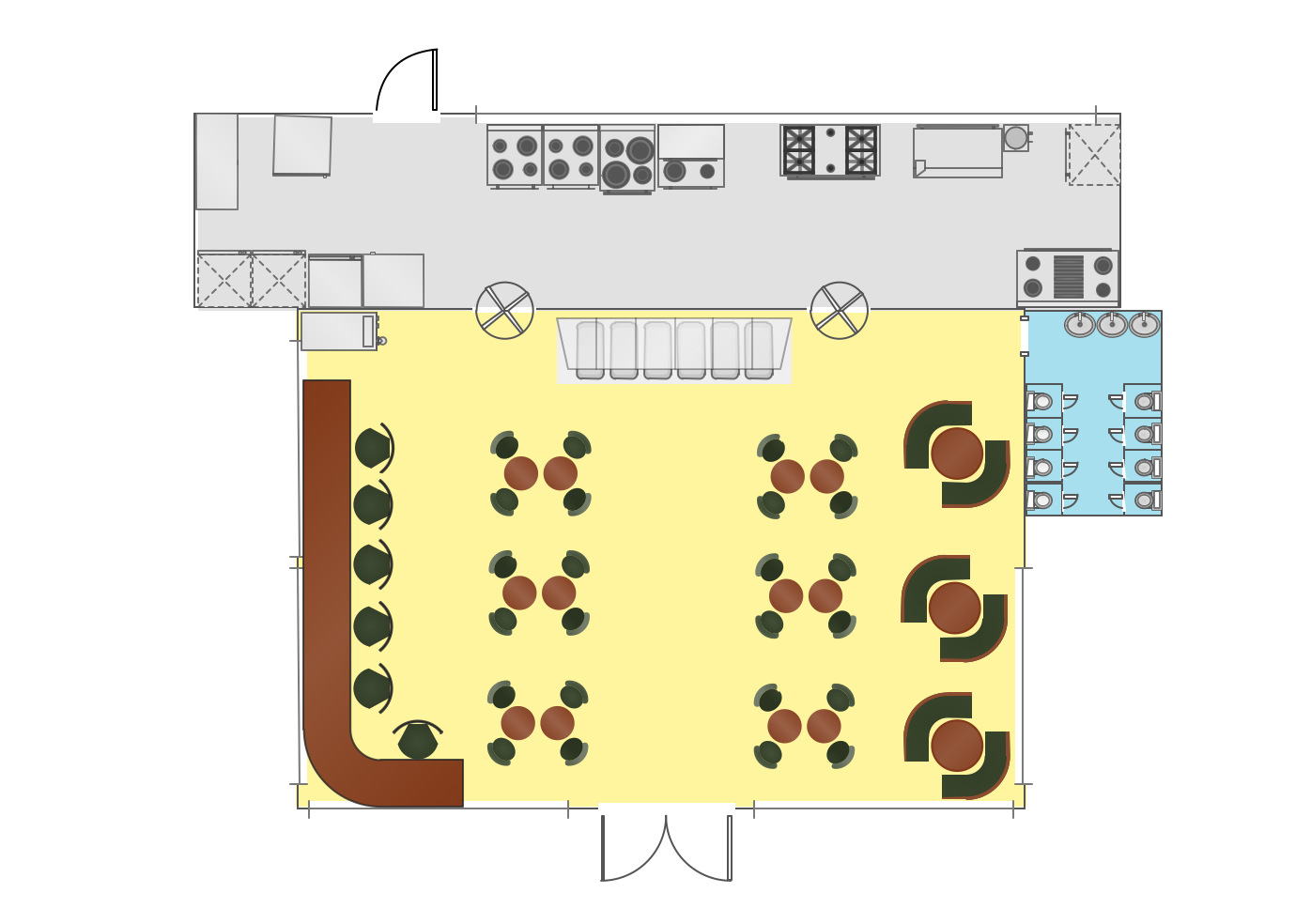
Working as an interior designer who implies that there is more of an emphasis on functional design, the effective use of space and planning, undertaking the projects that include such processes as arranging the basic layout of the spaces within some building, you might find the ConceptDraw DIAGRAM interior design drawing software.
Basic Network Diagram

Anyone Have an ERD Symbols Quick Reference?

But anyone have an ERD symbols quick reference? Detailed reference information for them is represented at the tables.
This telecom diagram sample illustrates the call shop solution. It was designed on the base of the Wikimedia Commons file: Call shops.jpg.
[commons.wikimedia.org/ wiki/ File:Call_ shops.jpg]
This file is licensed under the Creative Commons Attribution-Share Alike 3.0 Unported license. [creativecommons.org/ licenses/ by-sa/ 3.0/ deed.en]
"A call shop is a business providing on-site access to telephones for long-distance calling in countries without widespread home long-distance service. Calls may be prepaid or postpaid." [Call shop. Wikipedia]
The telecommunication diagram example "Call shop solution" was created using the ConceptDraw PRO diagramming and vector drawing software extended with the Computers and Communications solution from the Illustration area of ConceptDraw Solution Park.
Telecom diagram

Guesthouse Network. WIFI network to my guest house

This sample was created in ConceptDraw DIAGRAM diagramming and vector drawing software using the Computer and Networks solution from Computer and Networks area of ConceptDraw Solution Park.
- Bank ATM use case diagram | How to Create a Bank ATM Use Case ...
- How to Create a Bank ATM Use Case Diagram | UML use case ...
- Lodge Wiring Diagram
- Bank System | Banking System | Class UML Diagram for Bank ...
- Sample Network Diagram For Banks
- Class UML Diagram for Bank Account System | Bank Sequence ...
- Bank Sequence Diagram | UML use case diagram - Banking system ...
- How to Create a Bank ATM Use Case Diagram | Process Flowchart ...
- Design elements - Bank UML composite structure diagram | Design ...
- UML Component for Bank | UML Component Diagram | Banking ...
- ERD | Entity Relationship Diagrams, ERD Software for Mac and Win
- Flowchart | Basic Flowchart Symbols and Meaning
- Flowchart | Flowchart Design - Symbols, Shapes, Stencils and Icons
- Flowchart | Flow Chart Symbols
- Electrical | Electrical Drawing - Wiring and Circuits Schematics
- Flowchart | Common Flowchart Symbols
- Flowchart | Common Flowchart Symbols