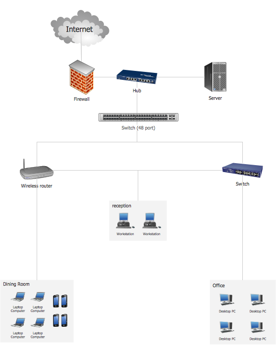
Hybrid Network Topology

This is example of the Hybrid network topology.
Network topology is the topological structure of the computer network. There are many types of the network topologies: bus, star, ring, mesh topology, but the most popular is the hybrid topology.
Wireless Network Topology

Wireless network topology shows how the computers connect each other when there is no physical connection. The computers communicate each using the wireless devices.
Cisco Network Topology. Cisco icons, shapes, stencils and symbols

Any Cisco equipment on the network are named like node. Network diagram topology commonly designed within connected nodes. Cisco icons are worldwide acknowledged and mainly established as standard icons for network diagrams. You may use them loosely, but you may not rework them.
The Cisco Network Diagram shows how signals act on the networked devices, or how data routes on the network from one device to the other. There are number of physical network typologies that engineers use while constructing computer networks.
Ring Network Topology

OSPF Network. Computer and Network Examples

This example was created in ConceptDraw DIAGRAM using the Computer and Networks Area of ConceptDraw Solution Park and shows the OSPF diagram.

Personal area (PAN) networks. Computer and Network Examples
 networks")
This example was created in ConceptDraw DIAGRAM using the Computer and Networks Area of ConceptDraw Solution Park and shows the Personal area network.
Hotel Network Topology
 Computer Network Diagrams
Computer Network Diagrams solution extends ConceptDraw DIAGRAM software with samples, templates and libraries of vector icons and objects of computer network devices and network components to help you create professional-looking Computer Network Diagrams, to plan simple home networks and complex computer network configurations for large buildings, to represent their schemes in a comprehensible graphical view, to document computer networks configurations, to depict the interactions between network's components, the used protocols and topologies, to represent physical and logical network structures, to compare visually different topologies and to depict their combinations, to represent in details the network structure with help of schemes, to study and analyze the network configurations, to communicate effectively to engineers, stakeholders and end-users, to track network working and troubleshoot, if necessary.
Network Topology

10Base-T Star Network Topology
Bus Topology Diagram
Common Network Topologies
Fully Connected Network Topologies
Ring Network Topologies
Mesh Network Topologies
With more than 2 000 pre-designed network elements you can design own Network Topology of the simple LAN, WAN, etc.
Complete Network Topology

A complete (fully connected) topology is a network topology in which there is a direct link between all pairs of nodes. In a fully connected network with n nodes, there are n(n-1)/2 direct links. Networks designed with this topology are usually very expensive to set up, but provide a high degree of reliability due to the multiple paths for data that are provided by the large number of redundant links between nodes.
- Topologies Network Pdf Free Download
- Cisco Network Templates | Application Of Hybrid Topology Pdf
- Hotel Network Topology Diagram | Hybrid Network Topology | Fully ...
- Campus Area Network Pdf
- Lan Wan Man Pan Pdf Download
- Advantages And Disadvantages Of Metropolitan Area Network Pdf
- Lan Wan Man Network Pdf
- Network Lan Wan Man Pdf
- Computer Network Architecture. Computer and Network Examples ...
- Personal Area Network Advantages And Disadvantages Pdf
- ERD | Entity Relationship Diagrams, ERD Software for Mac and Win
- Flowchart | Basic Flowchart Symbols and Meaning
- Flowchart | Flowchart Design - Symbols, Shapes, Stencils and Icons
- Flowchart | Flow Chart Symbols
- Electrical | Electrical Drawing - Wiring and Circuits Schematics
- Flowchart | Common Flowchart Symbols
- Flowchart | Common Flowchart Symbols