Cisco Network Topology. Cisco icons, shapes, stencils and symbols
")
Any Cisco equipment on the network are named like node. Network diagram topology commonly designed within connected nodes. Cisco icons are worldwide acknowledged and mainly established as standard icons for network diagrams. You may use them loosely, but you may not rework them.
The Cisco Network Diagram shows how signals act on the networked devices, or how data routes on the network from one device to the other. There are number of physical network typologies that engineers use while constructing computer networks.
The vector stencils library "Computers and network isometric" contains 56 3D clipart images of computer and network devices and equipment for drawing network diagrams.
The clip art example "Computers and network isometric - Vector stencils library" was created using the ConceptDraw PRO diagramming and vector drawing software extended with the Computer and Networks solution from the Computer and Networks area of ConceptDraw Solution Park.
The clip art example "Computers and network isometric - Vector stencils library" was created using the ConceptDraw PRO diagramming and vector drawing software extended with the Computer and Networks solution from the Computer and Networks area of ConceptDraw Solution Park.
Laptop

DDCS

Server

Webcam

Wireless Network Storage

Personal computer

VoIP phone

Fax

Plotter

Mobile phone

Feature phone

Printer

Satellite dish

Satellite antenna

Automatic-tracking satellite dish
Wireless access point

Wireless router

Router

Network switch

Network device

Mobile GPS Terminal

GPS phone

Television antenna

Radio tower

Base station

Satellite

In-vehicle satellite telecommunication

Satellite dishes on ship

Airplane

Internet

Man

Woman

Call-center

Honeycomb

Mountain

Radio waves

Radio waves

Tower block

Office building

House

House

Globe

Wireless security camera

Truck

Tree

Conifer tree

1U hub / switch

2U hub / switch

1U server

2U Server

3U Server

4U Server

Communications satellite

Car

Radio waves

Firewall

The vector stencils library "Electrical circuits" contains 49 element symbols of electrical and electronic devices, including ignitors, starters, transmitters, circuit protectors, transducers, radio and audio equipment.
Use it for drawing electronic circuit diagrams and electrical schematics in the ConceptDraw PRO diagramming and vector drawing software extended with the Electrical Engineering solution from the Engineering area of ConceptDraw Solution Park.
www.conceptdraw.com/ solution-park/ engineering-electrical
Ground

Equipotentiality

Igniter plug

Junction

Chassis

Chassis 2

Capacitor

Variable capacitor

Capacitor 2

Variable capacitor 2

Antenna

Antenna 2

Circuit breaker

Fuse

Fuse 2

Alarm fuse

Alarm fuse 2

Circular generic component

Rectangular generic component

Transducer

Capacitive transducer

Non-capacitive transducer

Recording pickup head

Reproducing pickup head

Positive pulse

Negative pulse

Alternating pulse

Saw tooth

Positive step function

Negative step function

Explosive squib

Sensing link squib

Squib ignitor

Unspecified material

Solid material

Semiconducting material

Liquid

Insulating material

Gas

Electret

Surge protector

Multigap surge protector

Valve surge protector

Electrolytic surge protector

Carbon block surge protector

Protective gap surge protector

Sphere gap surge protector

Horn gap surge protector

Circuit breaker

Baseball Diagram – Baseball Field – Corner View – Template

How To use House Electrical Plan Software

You can use many of built-in templates, electrical symbols and electical schemes examples of our House Electrical Diagram Software.
ConceptDraw is a fast way to draw: Electrical circuit diagrams, Schematics, Electrical Wiring, Circuit schematics, Digital circuits, Wiring in buildings, Electrical equipment, House electrical plans, Home cinema, Satellite television, Cable television, Closed-circuit television.
House Electrical Plan Software works across any platform, meaning you never have to worry about compatibility again. ConceptDraw PRO allows you to make electrical circuit diagrams on PC or macOS operating systems.

Network Diagram Software LAN Network Diagrams & Diagrams for LAN Physical Office Network Diagrams


Audio Visual Connectors Types

Residential Electric Plan

The vector stencils library "Telecom equipment" contains 11 hardware clipart icons of telecommunication devices for drawing computer network diagrams and equipment layouts.
"In telecommunication, a communications system is a collection of individual communications networks, transmission systems, relay stations, tributary stations, and data terminal equipment (DTE) usually capable of interconnection and interoperation to form an integrated whole. The components of a communications system serve a common purpose, are technically compatible, use common procedures, respond to controls, and operate in union. Telecommunications is a method of communication." [Communications system. Wikipedia]
"A basic telecommunication system consists of three primary units that are always present in some form: (1) A transmitter that takes information and converts it to a signal. (2) A transmission medium, also called the "physical channel" that carries the signal. ... (3) A receiver that takes the signal from the channel and converts it back into usable information." [Telecommunication. Wikipedia]
The clip art example "Telecom equipment - Vector stencils library" was created using the ConceptDraw PRO diagramming and vector drawing software extended with the Telecommunication Network Diagrams solution from the Computer and Networks area of ConceptDraw Solution Park.
Andrew multiband high / low power splitter

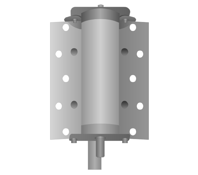
Andrew multi-band indoor omnidirectional antenna

Panel sector directional antenna
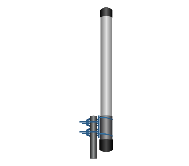
Omni directional antenna
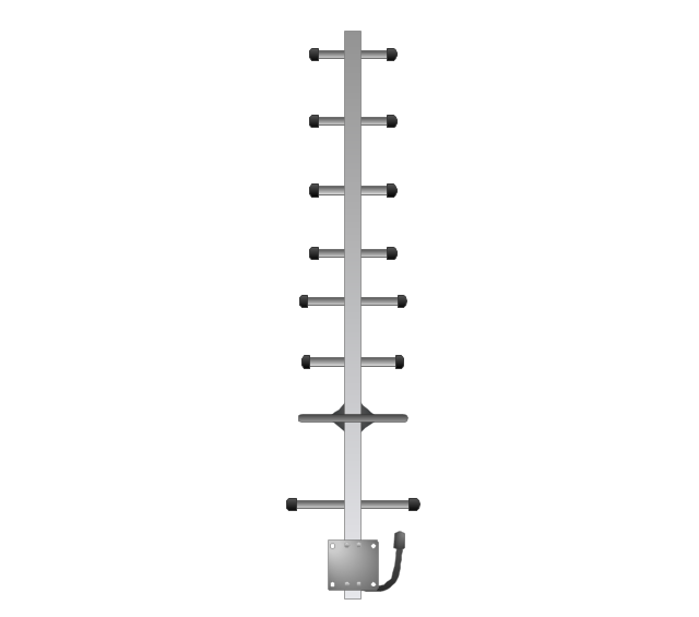
Yagi directional antenna
Yagi integrated downconverter

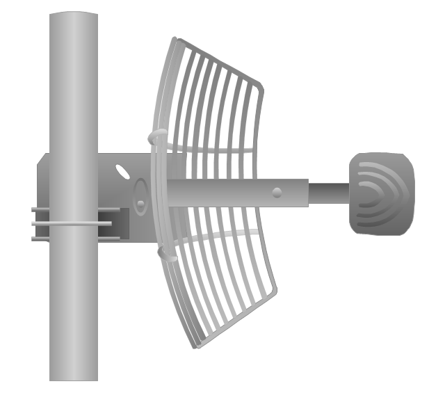
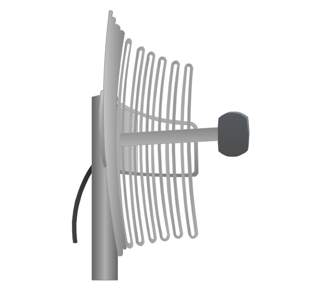
Grid antenna
Loop antenna
FireTide HotPort® 6000 wireless mesh nodes
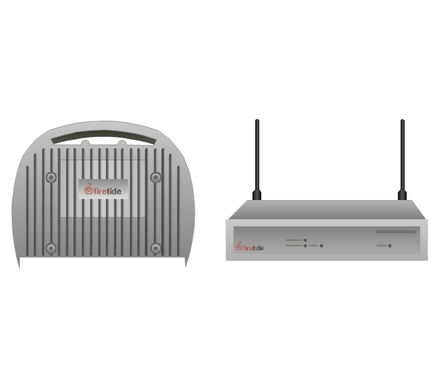
FireTide HotPoint® wireless access point
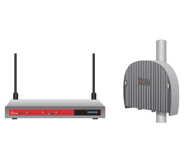
FireTide HotClient Customer Premises Equipment (CPE)
-telecom-equipment---vector-stencils-library.png--diagram-flowchart-example.png)
The vector stencils library "Telecommunication networks" contains 32 clipart images of telecommunication network devices and equipment for drawing telecom network diagrams.
"A telecommunications network is a collection of terminal nodes, links and any intermediate nodes which are connected so as to enable telecommunication between the terminals.
The transmission links connect the nodes together. The nodes use circuit switching, message switching or packet switching to pass the signal through the correct links and nodes to reach the correct destination terminal.
Each terminal in the network usually has a unique address so messages or connections can be routed to the correct recipients. The collection of addresses in the network is called the address space." [Telecommunications network. Wikipedia]
The clip art example "Telecommunication networks - Vector stencils library" was created using the ConceptDraw PRO diagramming and vector drawing software extended with the Telecommunication Network Diagrams solution from the Computer and Networks area of ConceptDraw Solution Park.
Internet

Globe

Base station

Satellite dish

Satellite dish

Communications satellite

Wireless cell tower

Radio waves

Radio waves

Cellular phone

Server

Laptop computer

Desktop computer

Car

Satellite truck

House

House

Office building

Mountain

Tree

Tree

User

Call-center

Multi-storey

Antenna

Router

IP phone

Fax

Network cell

IP Camera

Wireless router

Networking device

How to Make Audio and Video Connections

Electrical Symbols — Electrical Circuits

Electrical and electronic circuits can be complicated. Making a drawing of the connections to all the component parts in the circuit's load makes it easier to understand how circuit components are connected. Drawings for electronic circuits are called "circuit diagrams". Drawings for electrical circuits are called "wiring diagrams".
26 libraries of the Electrical Engineering Solution of ConceptDraw PRO make your electrical diagramming simple, efficient, and effective. You can simply and quickly drop the ready-to-use objects from libraries into your document to create the electrical diagram.
Audio and Video Connections Explained

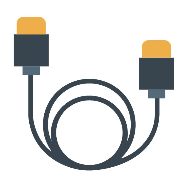
The vector stencils library "TV, Photo and Video" contains 52 television, digital photo and video icons.
Use it to design your audio, video and multimedia illustrations, presentations, web pages and infographics with ConceptDraw PRO diagramming and vector drawing software.
The vector stencils library "TV, Photo and Video" is included in the Audio, Video, Media solution from the Illustration area of ConceptDraw Solution Park.
Television set

TV set

Portable TV set

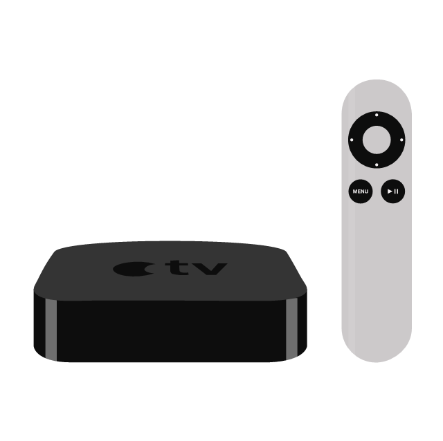
Apple TV
Wide LCD monitor

Plasma TV

HD screen

Antenna TV

Retro TV

Digital camera

Compact camera 1

Compact camera 2

Photo camera

Camera shutter

Photo images

Photos

Video cassette

Cassette

VHS

Film reel

Video

Movie

Clapboard

Clapper

Video cam

Video camera

Handy cam

Digital camcorder

Movie camera

Video record

Projector

Movie projector 1

Movie projector 2

Video projector 3

Overhead projector

Projector screen

Cinema

DVD video recorder

Video player

DVD player 1
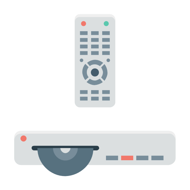
DVD player 2

Remote

Remote control 1

Remote control 2

HDMI video cable
CCTV dome camera

Dome camera

Surveillance camera

CCTV camera 1

CCTV camera 2

Security camera 1

Security camera 2

Local area network (LAN). Computer and Network Examples
. Computer and Network Examples")
ConceptDraw - Perfect Network Diagramming Software with examples of LAN Diagrams. ConceptDraw Network Diagram is ideal for network engineers and network designers who need to draw Local Area Network diagrams.
- Microwave Earth Antenna Visio Stencils
- Hf Antenna Visio Stencil
- Parabolic Visio Antenna
- Cisco Omni Directional Antenna Visio Stencils
- Cisco network topology - Vector stencils library | Terrestrial Antenna ...
- Antenna Stencil Visio
- Visio Stencils Radio
- Visio Stencil Gps
- Visio Antenna Connection
- Telecommunications Network | Comtech Antenna Visio Stencils
- Sector Antennas For Visio
- Apple Tv Visio Stencil
- Visio Stencils Motorola
- Visio Stencils For Electronic Sensors
- Cell Tower Visio Stencil
- Visio Stencil Tv Antenna
- Tv Antenna Visio Stencil
- Visio Stencil Antenna
- Visio Template Radar Antenna
- Voip Visio Stencils
- ERD | Entity Relationship Diagrams, ERD Software for Mac and Win
- Flowchart | Basic Flowchart Symbols and Meaning
- Flowchart | Flowchart Design - Symbols, Shapes, Stencils and Icons
- Flowchart | Flow Chart Symbols
- Electrical | Electrical Drawing - Wiring and Circuits Schematics
- Flowchart | Common Flowchart Symbols
- Flowchart | Common Flowchart Symbols