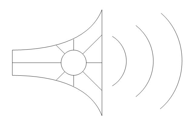
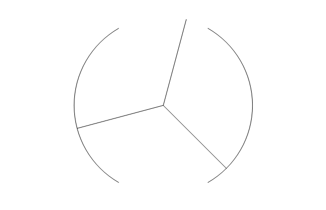
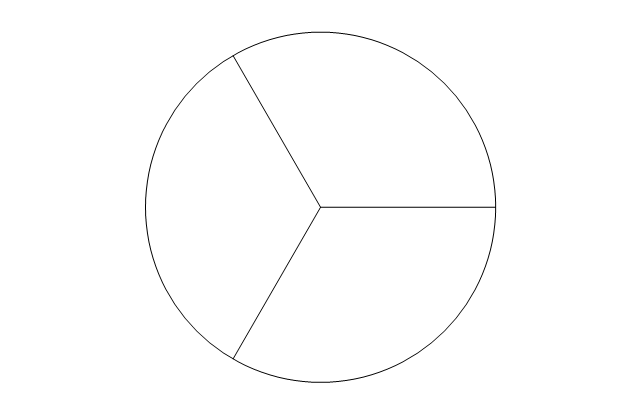
The vector stencils library "Electrical circuits" contains 49 element symbols of electrical and electronic devices, including ignitors, starters, transmitters, circuit protectors, transducers, radio and audio equipment.
Use it for drawing electronic circuit diagrams and electrical schematics in the ConceptDraw PRO diagramming and vector drawing software extended with the Electrical Engineering solution from the Engineering area of ConceptDraw Solution Park.
www.conceptdraw.com/ solution-park/ engineering-electrical
Ground

Equipotentiality

Igniter plug

Junction

Chassis

Chassis 2

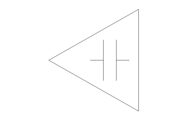
Capacitor

Variable capacitor

Capacitor 2

Variable capacitor 2

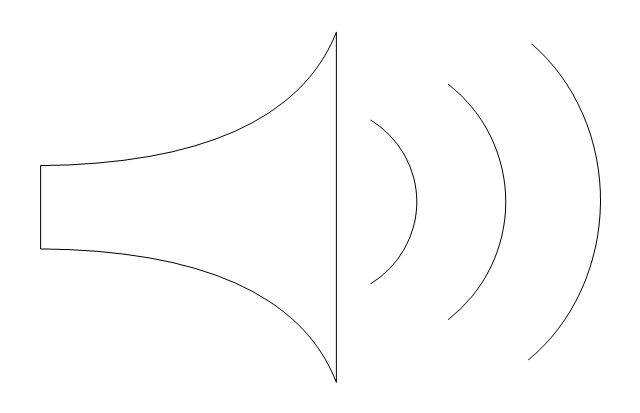
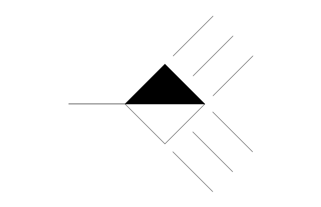
Antenna

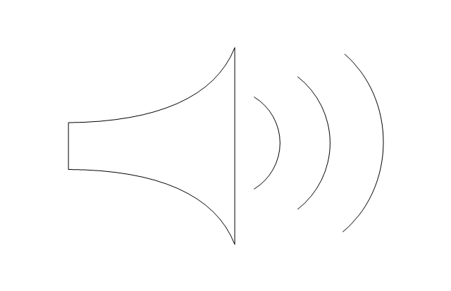
Antenna 2

Circuit breaker

Fuse

Fuse 2

Alarm fuse

Alarm fuse 2

Circular generic component

Rectangular generic component

Transducer

Capacitive transducer

Non-capacitive transducer

Recording pickup head

Reproducing pickup head

Positive pulse

Negative pulse

Alternating pulse

Saw tooth

Positive step function

Negative step function

Explosive squib

Sensing link squib

Squib ignitor

Unspecified material

Solid material

Semiconducting material

Liquid

Insulating material

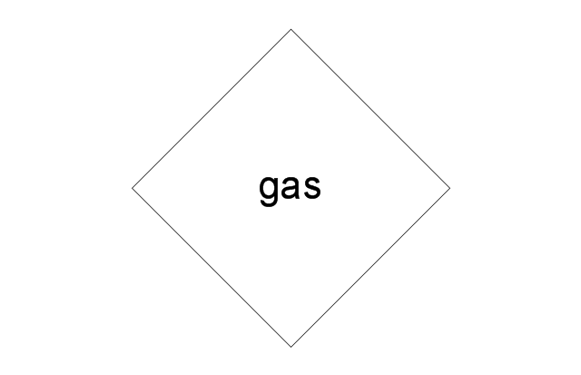
Gas

Electret

Surge protector

Multigap surge protector

Valve surge protector

Electrolytic surge protector

Carbon block surge protector

Protective gap surge protector

Sphere gap surge protector

Horn gap surge protector

Circuit breaker

Electrical Symbols — Analog and Digital Logic

How To use House Electrical Plan Software


Electrical Symbols — Switches and Relays

Electrical Symbols — Thermo

Electrical Symbols — Electrical Circuits

Electrical Symbols — Resistors

The vector stencils library "Alarm and access control" contains 80 shapes of digital proximity equipment, locking hardware, and access control equipment. Use it for drawing security and access plans of intrusion systems, time and attendance systems, and card and code access control security systems with ConceptDraw PRO software extended with the Security and Access Plans solution from the Building Plans area of ConceptDraw Solution Park.
Card reader with keypad
Biometric access
Card access
Keypad device
Keypad
Security keypad
Horn / siren
Weatherproof horn / siren
Horn / strobe
Strobe

Card reader with time
Turnstile
Revolving door
Traffic arm
Vehicle loop detector
Smoke detector
Heat detector
Gas detector
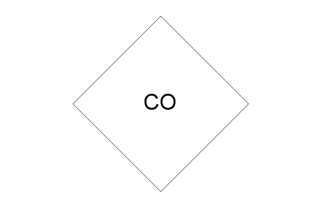
Carbon monoxide detector
Flood sensor
Electronic lock
Exit device
Pushbutton

Panic button

Camera with keypad
Camera

Camera with intercom
Camera with card reader
Security window screen
Window contact sensor
Vibration / shock sensor
Screen alarm
Glass break detector
Door contact sensor
Floor mat

Driveway sensor
Overhead door contact sensor
Wall motion sensor
Floor motion sensor

Security control unit
Security door contact
Security control panel
Security card reader
Motion detector

Master intercom

Magnetic lock, security door alarm
Intercom unit
Electric door strike
Electric door opener
Door buzzer
Door chime
Doorbell
Volumetric capacity detector
Siren
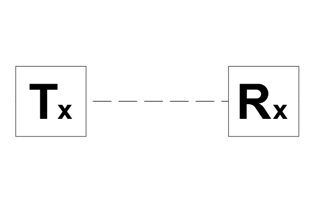
Receiver

PIR field of view

Mains supply power source

Infrared detector
Heat detector
Foil on glass detector
Dial-up remote equipment
Beam fence disturbance
User control keyswitch
User control digital keypad
Ultrasonic transceiver
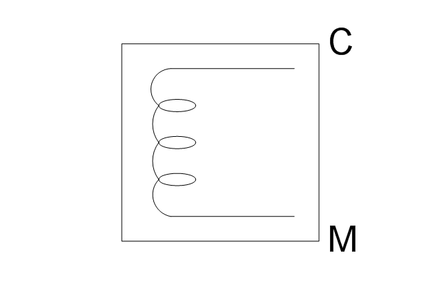
Transformer

Space detection device
Slave tape dialer
Slave digital communicator
Remote zone annunciator
Passive infrared
Microwave transceiver
Line cut monitor
Infrasonic
Foil

Emergency power / battery
Dual technology device
Control unit

Contact switch surface

Contact switch flush
Electrical Symbols — VHF UHF SHF

Home Electrical Plan

Electrical Symbols — Delay Elements

In searching of alternative to MS Visio for MAC and PC with ConceptDraw PRO

Electrical Symbols — Composite Assemblies

Electrical Symbols — Logic Gate Diagram

Electrical Symbols — Transmission Paths

- Alarm Visio Shapes
- Visio Shapes Sensors
- Ms Visio Stencils Electronic
- Visio Stencils Alarm
- Analog Phone Visio Stencil
- Electrical circuits - Vector stencils library | Computers and network ...
- Antenna Stencil Visio
- Visio Stencils Electrical
- Electrical circuits - Vector stencils library | Baseball Field Sample ...
- Visio Stencils Electrical Engineering
- Visio Shapes Engine Sensors
- Motion Detector Visio Stencil
- How To use House Electrical Plan Software | Electrical circuits ...
- Electrical circuits - Vector stencils library | Electrical Symbols ...
- Visio Templates Electronic Components
- Cisco Optical. Cisco icons , shapes , stencils and symbols | Electrical ...
- Visio Stencil Elevator
- Visio Stencils Envelope
- Visio Electrical Engineering Stencils