Importance of House Electrical PlansHow to Create Electrical Layoutswith ConceptDraw DIAGRAM App
Importance of Electrical Layout Drawing
Electrical layout drawings are technical drawings that provide visual representations of circuits and electrical systems. These include electrical layouts and electrical designs created by electrical engineers for electricians and other workers. Electrical drawings offer valuable benefits to construction projects, help carefully thought out the electrical systems, lighting, power distribution, load flow, digital communication, the layout of the electrical wires, equipment, and devices, precisely install, efficiently maintain, and repair electrical systems.
Clear visualization of documentation using Electrical Diagrams increases efficiency in planning and realization the electrical and building projects, helps to explain complex electrical systems and interaction of numerous components in a visual graphical format, and efficiently distribute power to equipment and appliances. Electrical designs are useful to provide electrical safety procedures and smooth operation, minimizing disruptions and failures, and maximizing productivity. They ensure safety and reduce risks of technical errors, as well as accidents or injuries during installation or troubleshooting.
House electrical plan drawing may look at first as a complex task as it requires a lot of expertise, but we offer you a way to simplify drawing work. Start wiring diagram with an all-inclusive floor plan software — ConceptDraw DIAGRAM. It contains libraries with a large range of lighting and electrical symbols and ready-to-use samples and templates of electrical plans and electrical layouts.

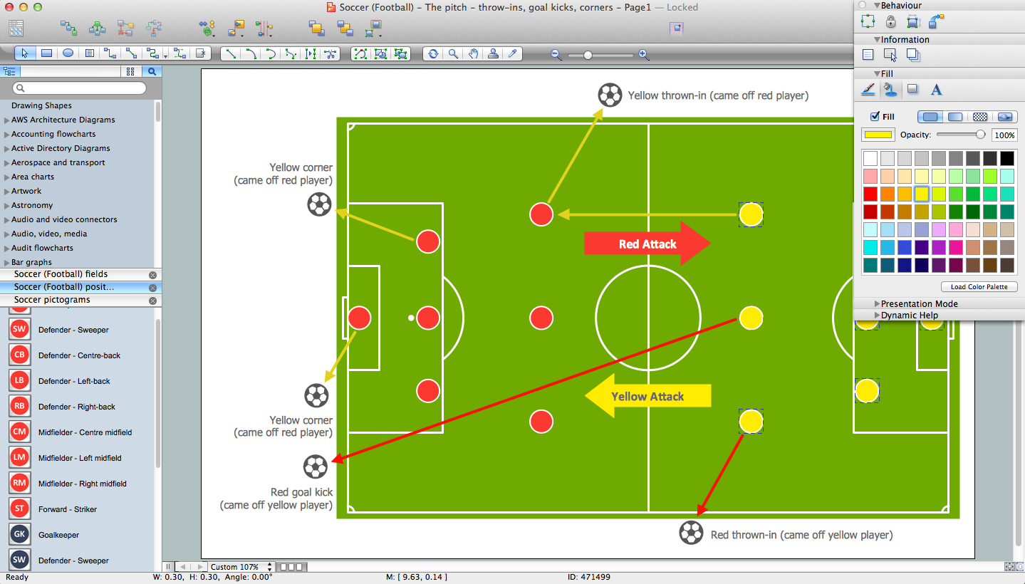
Need to visualize a workflow instead of an electrical layout? Use flowcharts to map steps, decisions, and process logic in a clear visual format.
Types of Electrical Plans for Houses
Electrical Plans have great value in the construction of any building, in particular a residential block of flats or a private house. House electrical wiring diagram is necessary to plan out the locations of your switches, outlets, dimmers, and lights, and to understand how you will connect them, before wiring your home.
You don't need complicated drawing CAD tools, if you aren't drawing professionals. So ConceptDraw is your best solution when you map out utilization, decor, hobbies and the activities of the various residents.
ConceptDraw DIAGRAM is a fast way to draw different types of Electrical plans:
| # | Options |
|---|---|
| 1. | House electrical plan |
| 2. | Electrical circuit diagrams |
| 3. | Electrical schematics |
| 4. | Electrical wiring |
| 5. | Electrical equipment |
| 6. | Circuit schematics |
| 7. | Digital circuits |
| 8. | Wiring in buildings |
| 9. | Satellite television |
| 10. | Cable television |
| 11. | Closed-circuit television |
| 12. | Home floor plans |
| 13. | House electrical wiring diagram |
| 14. | Home cinema |
Electrical plans and flowcharts solve different visual tasks. Electrical layouts show wiring, outlets, and equipment placement, while flowcharts are used to represent process steps, decisions, and system logic.
Designing Lighting Layouts and Switch Positions
You can use many of the built-in templates and examples of our House Electrical Planning App. Start with the exact template you need, then customize it to fit your needs with more than 1000 electrical symbols and you will find an expected result in minutes.

Electric and Telecom Plans solution for ConceptDraw DIAGRAM software contains 6 libraries containing 334 objects:
Electrical library contains symbols for electrical drawings, circuit schematic and wiring diagrams.

Electrical and Telecom library contains symbols for electrical drawings of electrical and telecommunication equipment and wiring in buildings, communication centers, power plants and electrical distribution systems.

Switches library contains symbols for drawing electrical circuit and electric wiring on the house electrical plan.

Planning Outlet and Wiring Placement
Outlets library contains symbols for drawing electrical circuit schematic.

Video and Audio library contains symbols for drawing audio and video system design floor and building plans, cabling layouts, circuit schematic and wiring diagrams of video and sound reproduction systems.

Cable TV library contains symbols of CATV network equipment.

Incorporating Safety Measures and Codes
Ensuring safety measures is critical for any building, helps to promote safety and protect people's lives and properties. The electrical system is an area of increased danger and requires particular attention. Its safety is achieved through implementing precautions, establishing and complying with a set of codes, standards, and regulations for electrical wiring, electrical installations and equipment. The compliance of safety starts from the house electrical plan drawing and then safe installation of electrical wiring and then electrical systems and equipment in buildings of any type without exception (residential, commercial, and industrial).
Engineers working with electrical systems must prioritize safety to prevent injuries, accidents, and even fatalities during the installation of electrical systems and further use. These include relevant training and education, attentiveness, proper equipment selection, installation following the rules and requirements, regular equipment maintenance, risk assessment, compliance with codes and standards, turning off the power before working with electrical wiring, fire safety measures, grounding and bonding, and personal protective equipment.
How to Use Electrical Plan Drawing Software
ConceptDraw DIAGRAM electrical plan drawing software works across both platforms Apple macOS and Microsoft Windows, meaning you never have to worry about compatibility again. It allows you to make electrical circuit diagram of any complexity on PC or macOS operating systems. Use ConceptDraw DIAGRAM to create the electrical and telecommunication floor plans for design and construction based on the floor plans describing the relationships between rooms, spaces, and physical objects, and using included outlets, switches, fixtures, and other objects.
Commonly used symbols and their meaning for House Electrical Plan drawing.
| Symbol | Meaning | Symbol | Meaning |
|---|---|---|---|
 |
Ceiling mounted luminaire |  |
Enclosed ceiling luminaire |
 |
Wall light. Wall mounted fixture |  |
Multi-light bar. Light bar with glass globes. Number of bulbs can be specified |
 |
Down lighter |  |
Outdoor lighting |
 |
Batten fluorescent fixture. One-, two-, or three-lamp configuration can be specified |  |
Surface Fluorescent Light |
 |
Modular fluorescent fitting |  |
Pull-cord switch |
 |
Switch |  |
Switch, 1 and 2 pole |
 |
Switch, 2-way |  |
Multi-switch |
 |
Switch, intermediate |  |
Dimmer switches |
 |
Emergency light |  |
Illuminated emergency sign |
 |
Socket outlet |  |
Switched socket |
 |
Double socket |  |
Cable television outlet |
 |
Service panel. Service for a flush mounted or recessed electrical service panel |  |
Thermostat |
 |
Ceiling fan. Exhaust fan fixture |  |
Electro magnetic door hold open unit |
 |
Surface mounted heat or smoke detector |  |
Fire alarm sounder |
 |
City Fire Alarm Station |  |
Fire Alarm Station |
 |
Fire Alarm Bell |  |
Fire Alarm Central Station |
 |
Automatic Fire Alarm Device |  |
Main control or intake |
 |
Ground connection |  |
Doorbell |
 |
Push Button |  |
Buzzer |
 |
Annunciator |  |
Horn |
 |
Maid's Signal Plug |  |
Signal Central Station |
 |
Doorbell Chime |  |
Doorbell Transformer |
 |
Magnetic Door Hold |  |
Intercom |
 |
Telephone Key System |  |
Digital Satellite System |
 |
Inside Antenna |  |
Outside Antenna |
 |
Electric Motors |  |
Single Phase |
 |
Three of Polyphase |  |
Wall Mounted Electrical Junction Box for Hardware |
 |
Wall Mounted Telephone/Data Junction Box for Hardware |  |
Card Reader Access System |
 |
Emergency Release Button |  |
Motion Sensor |
 |
Electric Door Opener |  |
Watchman's Station |
 |
Watchman's Central Station |  |
Battery |
Examples
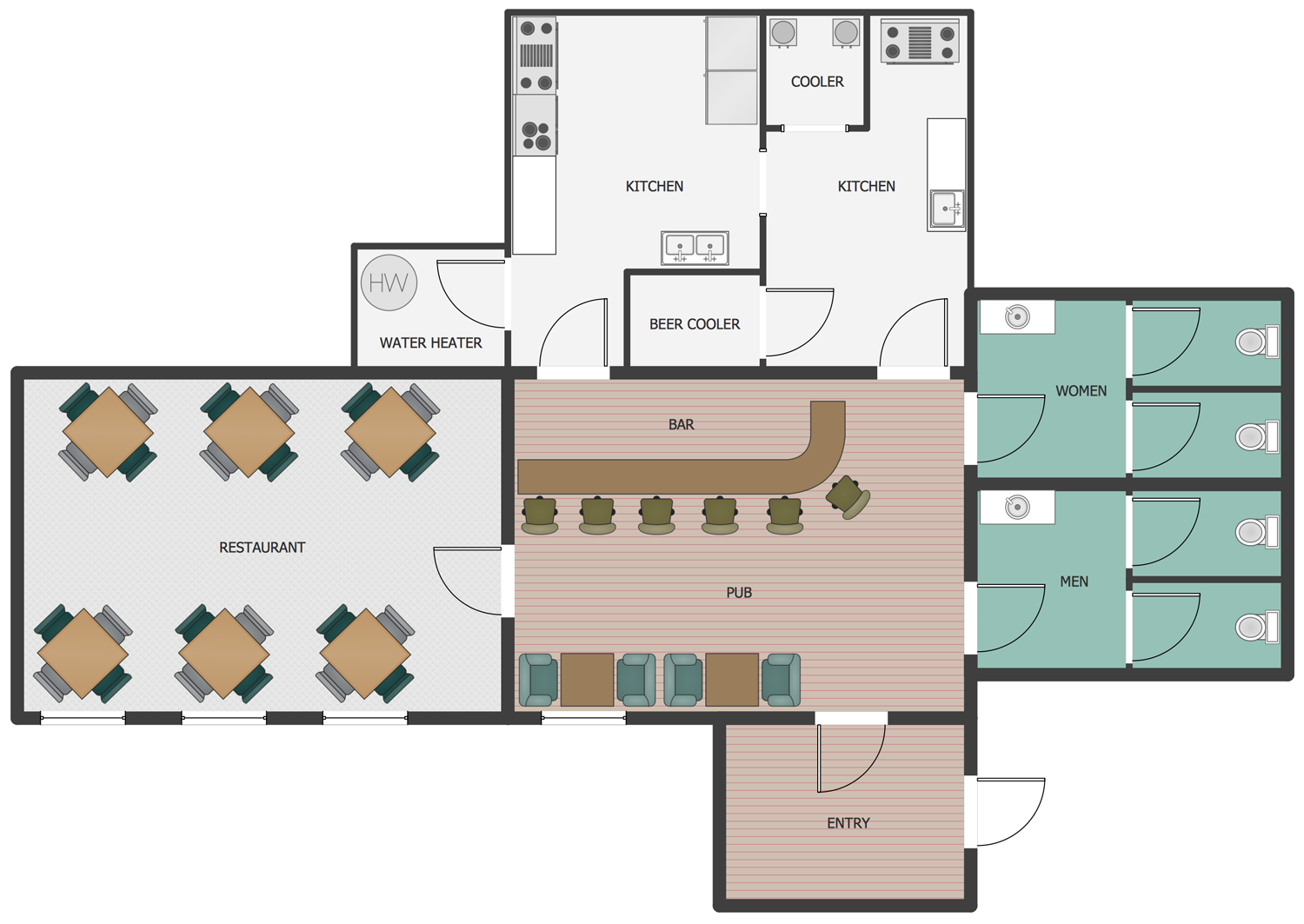
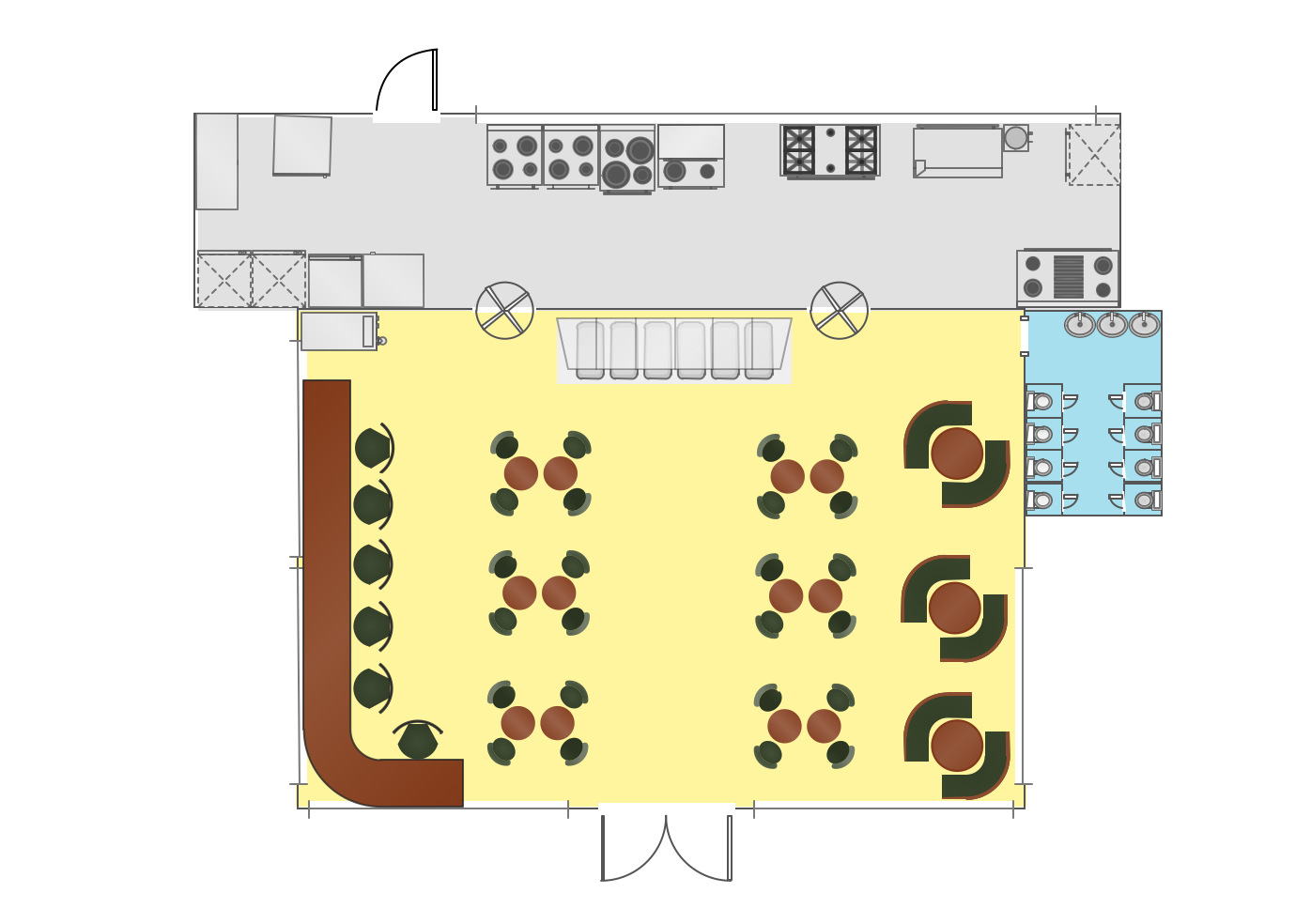
This simple small house electrical plan is created using ConceptDraw DIAGRAM enhanced with the Electric and Telecom Plans Solution from the ConceptDraw Solution Park.

These examples show the location of electrical devices in the building and the schemes of electric wiring.

Conclusion
The following features make ConceptDraw DIAGRAM the best house electrical layout software:
- You don't need to be an artist to draw professional looking diagrams in a few minutes.
- Large quantity of ready-to-use vector objects makes your drawing diagrams quick and easy.
- Great number of predesigned templates and samples give you the good start for your own diagrams.
- ConceptDraw DIAGRAM electrical wiring planner provides you the possibility to use the grid, rules and guides. You can easily rotate, group, align, arrange the objects, use different fonts and colors to make your diagram exceptionally looking.
- All ConceptDraw DIAGRAM documents are vector graphic files and are available for reviewing, modifying, and converting to a variety of formats: image, HTML, PDF file, MS PowerPoint Presentation, Adobe Flash, MS Visio.
- Using ConceptDraw STORE you can navigate through ConceptDraw Solution Park, managing downloads and updates. You can access libraries, templates and samples directly from the ConceptDraw STORE.
- If you have any questions, our free of charge support is always ready to come to your aid.