Data Flow Diagram Symbols. DFD Library

Entity Relationship Diagram Symbols

ERD symbols used for professional ERD drawing are collected in libraries from the Entity-Relationship Diagram (ERD) solution for ConceptDraw DIAGRAM.
ConceptDraw Arrows10 Technology
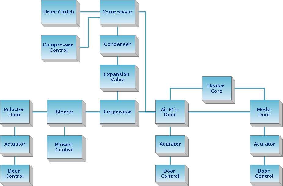
"Tree"- mode drawing works like that. Just select objects in your drawing and press Tree or Chain button to connect all of them just in one click.
Your diagram looks professional and it took only a moment to draw.
Star Network Topology

Use it to draw the physical and logical network topology diagrams for wired and wireless computer communication networks.

Storage area networks (SAN). Computer and Network Examples
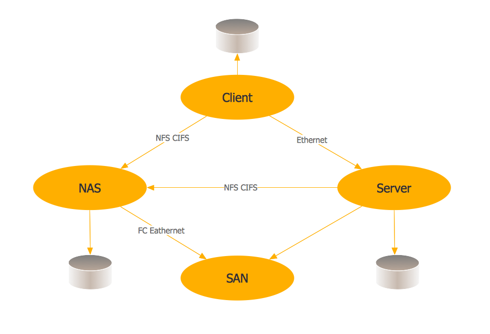
This example was created in ConceptDraw DIAGRAM using the Computer and Networks Area of ConceptDraw Solution Park. It shows the hybrid of Storage area network (SAN) and Network Attached Storage (NAS) technologies.

Software and Database Design with ConceptDraw DIAGRAM

UML diagramming; designing and prototyping Graphical User Interface (GUI); flowcharts, data flow diagrams; database and ERD diagramming (Chen ERD, Database Model diagram, Express-G, Martin ERD, ORM Diagrams and more); SSADM diagrams, Booch diagrams, Nassi-Shneiderman diagrams with special flowchart symbols.
Wide area network (WAN) topology. Computer and Network Examples

This example was created in ConceptDraw DIAGRAM using the Computer and Networks Area of ConceptDraw Solution Park and shows the Wide area network topology.
Tree Network Topology Diagram

Design Data Flow. DFD Library

Cross Functional Flowchart for Business Process Mapping
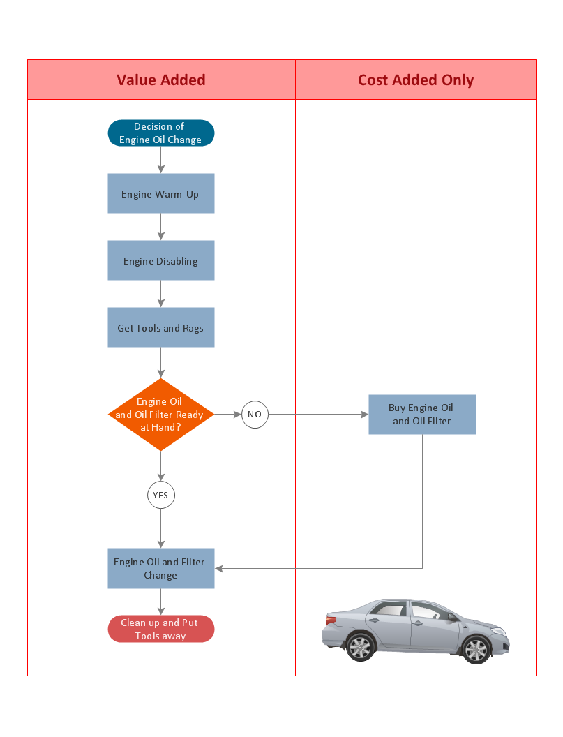
Use a variety of drawing tools, smart connectors and shape libraries to create flowcharts of complex processes, procedures and information exchange. Define and document basic work and data flows, financial, production and quality management processes to increase efficiency of you business.
- Wireless access point - Network diagram | Hotel Network Topology ...
- Data Flow Diagram | Basic Flowchart Symbols and Meaning ...
- Basic Flowchart Symbols and Meaning | Data Flow Diagram ...
- Process Flowchart | Data Flow Diagram Process | Basic Flowchart ...
- Microsoft Store
- Active Directory diagram - Asymmetric encryption | Design elements ...
- Electrical Symbols — Transmission Paths | Network Diagram ...
- Process Flowchart | Basic Flowchart Symbols and Meaning | Data ...
- Wired Connection Diagram
- How To use Switches in Network Diagram | VMware vNetwork ...
- ERD | Entity Relationship Diagrams, ERD Software for Mac and Win
- Flowchart | Basic Flowchart Symbols and Meaning
- Flowchart | Flowchart Design - Symbols, Shapes, Stencils and Icons
- Flowchart | Flow Chart Symbols
- Electrical | Electrical Drawing - Wiring and Circuits Schematics
- Flowchart | Common Flowchart Symbols
- Flowchart | Common Flowchart Symbols